TM 5-3810-207-20/TO 36C23-3-37-12
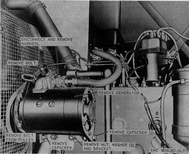
Figure 7. Generator assembly, removal and installation.
d.
Test and Adjustment.
(1)
Mechanical adjustments.
(a)
Disconnect
regulator
to
battery
cable.
(b)
Remove regulator cover (A, fig. 9).
(c)
Press down on the cutout relay
armature (B, fig. 9) until the contact
points
are
barely
touching.
Measure the airgap between the coil
core and the armature. The correct
airgap for the cutout relay is 0.048
inch.
Note.
Do not measure the cutout relay
airgap between the brass residual
pin in the coil and the armature.
(d)
Should the cutout relay airgap not
be as specified, bend the armature
stop up or down to obtain the proper
clearance.
Caution:
Make certain the cutout relay contact
bracket is in proper position to allow
both
contact
points
to
close
simultaneously.
(e)
Measure the clearance between the
contact points. The proper cutout
relay point opening is 0.035 inch.
(f)
If the cutout relay point opening is
not as specified, loosen the two
screws securing the cutout relay
contact bracket to the cutout relay
and raise or lower the cutout relay
31