
Now, refer to Sketch 2. Determine the routing for the boom foot cable and install deflecting pulleys where required. Run
the cable and install the solderless nipples at both Sheaves. Tighten the solderless nipple at the boom foot sheave.
Tension the spring about 2". Tighten the solder- less nipple at the control box after ascertaining that every part is in equal
tension.
REMOVE THE 3/16" ROD LOCKING THE ACTUATING ARM otherwise damage will occur during booming.
INSTALLING THE ALARM UNIT AND ELECTRICAL WIRING.
The alarm unit consists of a bell, a red light and an amber light. These must be mounted in such a position that it is plainly
audible and visible to the crane operator.
Bolt the bell in position in the crane cab using the two holes provided. Mount the lights either on the bell or at any place
where they are readily visible.
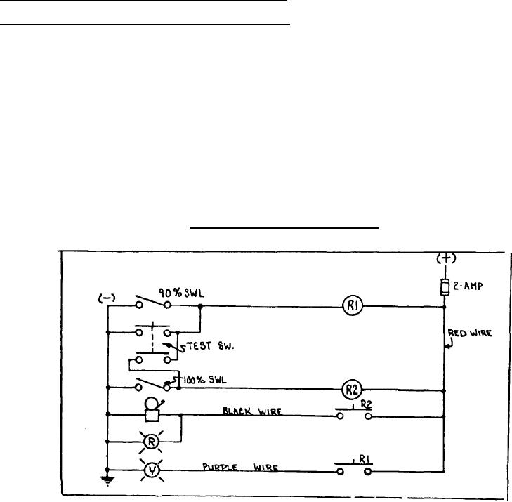
Remove the plastic cover from the connection box at the Control Box revealing the terminal strip. Connect one wire from
the BLACK terminal to the Bell and Red light. The other terminal of the bell and red light should be connected to ground.
Connect from the purple terminal to the amber warning light. (Other side of light to ground again).
Connect one more wire from the RED terminal at the Control Box to the live side of the crane's electrical supply by way of
a 2-amp fuse.
Depress the test button to check functioning of the circuit. The Bell should ring and the Red light should light.
REFER TO WIRING DIAGRAM. FIG. I.
2-1-14

