
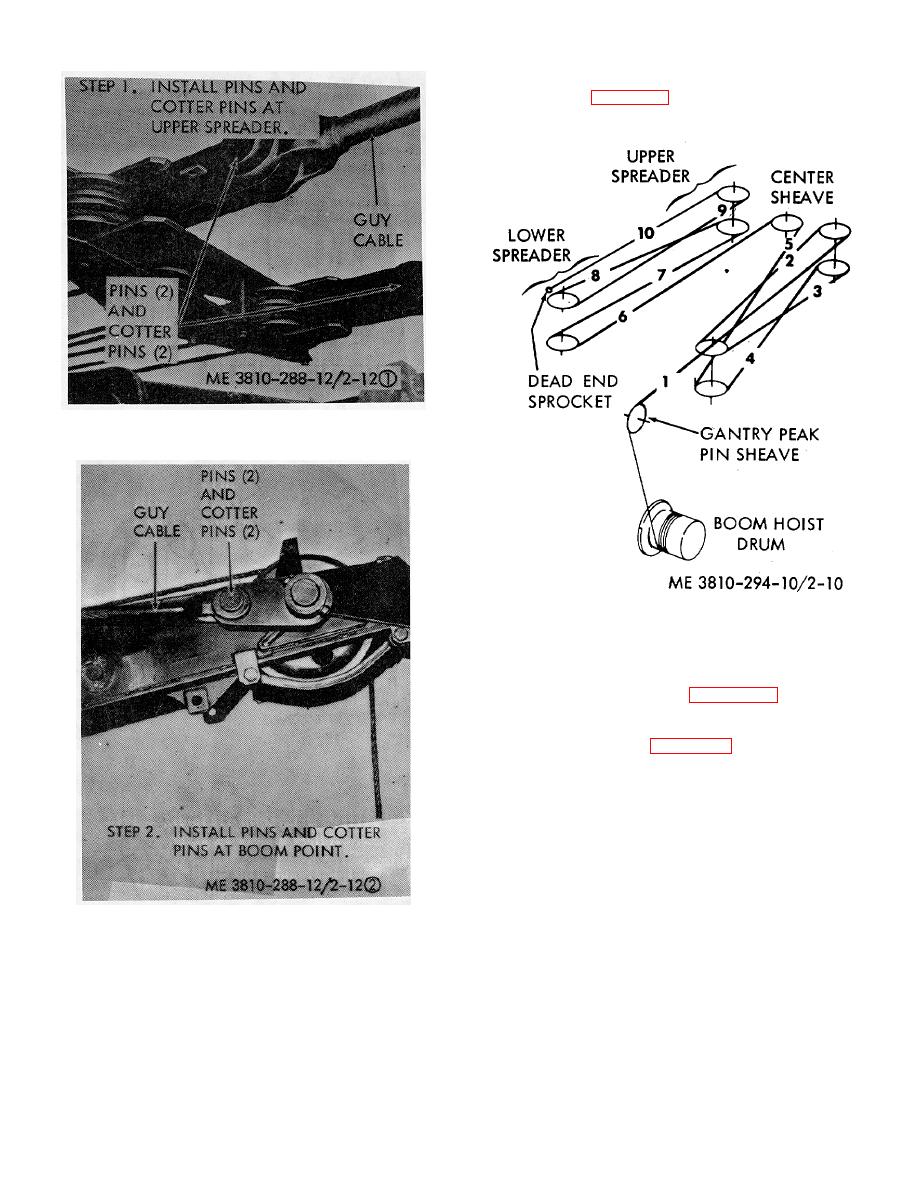
(4) Begin at the upper spreader center sheave
as illustrated in figure 2-10 and reeve the left side of the
upper spreader and lower spreader as shown. End at
the dead end socket on the gantry A-frame.
Figure 2-9. Guy cables, removal and installation (sheet
1 of 2).
Figure 2-10. Boom hoist line reeving.
(5) Beginning at the upper spreader center
sheave, reeve the right side of the upper spreader and
lower spreader as shown in figure 2-10. End at the
boom hoist drum.
(6) Secure the boom hoist line to the (boom
hoist drum as shown in figure 2-11 and spool the slack
cable on the drum.
Figure 2-9. Guy cables, removal and installation (sheet
2 of 2).
(2) Install the gantry spreader on the gantry A-
frame.
(3) Unroll and stretch the boom suspension
cable out on the ground on the right side of the boom.
2-5

