
TM 5-3810-300-24&P-3
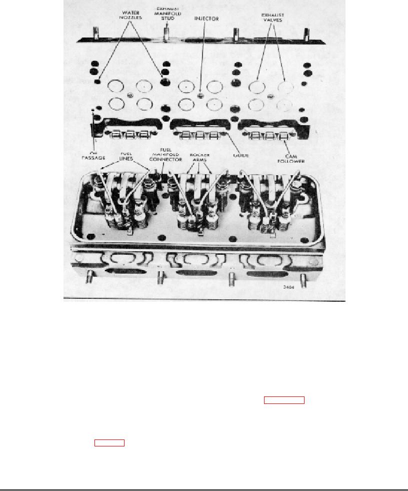
Fig. 2-Cylinder Head Assembly (Four Valve)
upper end and flared lower end of the injector tube
coolant at high velocity toward the sections of the
prevent water and compression leaks.
cylinder head which are subjected to the greatest heat.
No water space is provided around the injectors in very
The fuel inlet and outlet manifolds are cast as an integral
early four-valve cylinder heads. Therefore, no injector
part of the current cylinder heads. Tapped holes are
tubes are required in these heads.
provided for connection of the fuel lines at various points
along each manifold.
On former cylinder heads,
The exhaust passages from the exhaust valves of each
separate fuel manifolds are attached to the side of the
cylinder lead through a single port to the exhaust
head (refer to Section 2.4).
manifold. The exhaust passages and the injector tubes
are surrounded by engine coolant.
The water manifold is also cast as an integral part of the
cylinder head.
In addition, cooling of the above areas is further ensured
by the use of water nozzles (Figs. 5 and 6) pressed into
To seal compression between the cylinder head and the
the water inlet ports in the cylinder head. The nozzles
cylinder liner, separate laminated metal gaskets are
direct the comparatively cool engine
provided at each cylinder. Water and oil passages
between the cylinder head and cylinder block are
Page 30

