
TM 5-3810-300-24&P-3
1.2.1
VALVE AND INJECTOR OPERATING MECHANISM
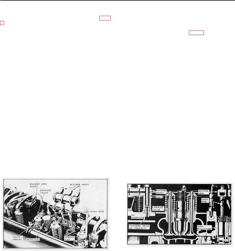
Three rocker arms are provided for each cylinder (Fig.
with the main oil gallery in the cylinder block. Oil from
1); the two outer arms operate the exhaust valves and
this passage flows through drilled passages in the rocker
the center arm operates the fuel injector.
shaft bracket bolts to the passages in the rocker arm
shaft to lubricate the rocker arms (Fig. 2).
Each set of three rocker arms pivots on a shaft
supported by two brackets. A single bolt secures each
Overflow oil from the rocker arms lubricates the exhaust
bracket to the top of the cylinder head. Removal of the
valves, valve bridges and cam followers. The oil then
two bracket bolts permits the rocker arm assembly for
drains from the top deck of the cylinder head through oil
one cylinder to be raised, providing easy access to the
holes in the cam followers, into the camshaft pockets in
fuel injector and the exhaust valve springs.
the cylinder block and back to the oil pan.
The rocker arms are operated by the camshaft through
The cam follower rollers are lubricated with oil from the
cam followers and short push rods extending through the
cam followers, oil picked up by the camshaft lobes and
cylinder head.
by oil emitted under pressure from milled slots in the
camshaft intermediate bearings.
Each cam follower operates in a bore in the cylinder
head. A guide for each set of three cam followers is
Lubrication of the rocker arms and shafts on aluminum
attached to the bottom of the cylinder head to retain the
cylinder heads is provided by a vertical oil passage at
cam followers in place and to align the cam follower
one end of the cylinder head that aligns with the oil
rollers with the camshaft lobes.
gallery in the cylinder block. Lubricating oil from this
vertical passage enters the rocker arm shaft bracket
A coil spring, inside of each cam follower, maintains a
through an elongated hole in the end of a spacer
pre-determined load on the cam follower to ensure
between the cylinder head and the rockershaft bracket
contact of the cam roller on the camshaft lobe at all
and fills the cavity surrounding the bracket hold-down
times.
bolt. The oil flows to the passages in the rocker arm
shaft and then to the cavity surrounding the hold-down
bolt in the opposite rocker shaft bracket. From this
bracket, which is assembled on top of one end of a
Lubrication
slotted intermediate spacer, oil passes along a slot in the
spacer to the adjacent bracket mounted on the other end
The valve and injector operating mechanism is lubricated
of the spacer. The intermediate spacers thus serve to
by oil from a longitudinal oil passage on the camshaft
channel lubricating oil from one valve and injector rocker
side of the cylinder head, which connects with the main
arm unit to the adjacent unit.
Fig. 2-Lubrication of Valve Operating Mechanism
Fig. 1-Valve and Injector operating Mechanism (Two-
Valve Head)
Page 41

