
TM 5-3810-300-24&P-3
1.2.2 EXHAUST VALVES
Recondition Exhaust Valve and Valve Seat Insert
Reface an exhaust valve which is to be reused as shown
in Fig. 14. The edge of the valve at the valve head must
not be less than 1/32" in thickness and still be within the
specifications shown in Fig. 16, after refacing.
Before installing either a new or used valve, examine the
valve seat insert in the cylinder head for proper valve
seating. The proper angle for the seating face of both
the valve and valve insert is 30.
The angle of the valve seat insert must be exactly the
same as the angle of the valve face to provide proper
seating of the valve.
When a new valve seat insert is installed or an old insert
is reconditioned, the work must be done with a grinding
tool as illustrated in Fig. 15.
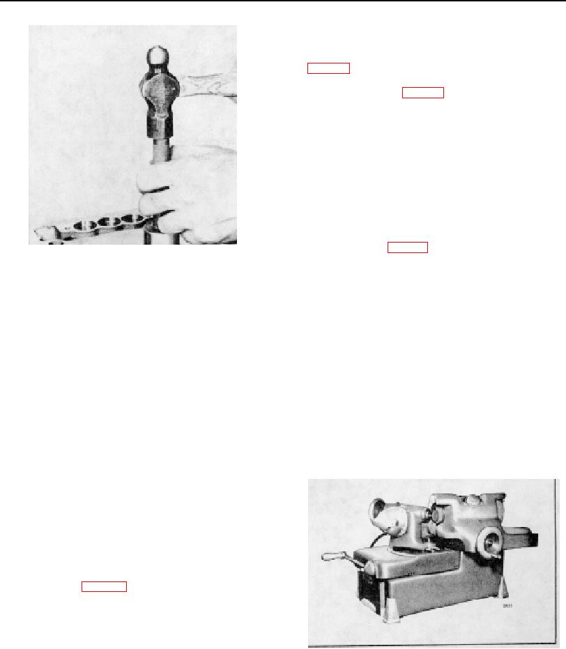
Fig. 13. Installing Valve Seat Insert
The eccentric grinding method for reconditioning a valve
3. Inspect the valve seat insert counterbore in the
seat insert is recommended. This method produces a
cylinder head for cleanliness, concentricity,
finer, more accurate finish since only one point of the
flatness and cracks. The counterbores in a two
grinding wheel is in contact with the valve seat at any
valve cylinder head have a diameter of 1.626" to
time. A micrometer feed permits the operator to feed the
1.627" and a depth of .3705" to .3845". The
grinding wheel into the work .001" at a time.
counterbores in a four valve cylinder head have
a diameter of 1.260" to 1.261" and a depth of
The eccentric valve seat grinder set J 8165, used to
.338" to .352". The counterbores must be
recondition or grind the valve seat inserts for a two valve
concentric with the valve guides within .003" total
cylinder head, consists of:
indicator reading. If required, use a valve seat
insert which is .010" oversize on the outside
1.
Grinder J 8165-1.
diameter.
2.
Dial gage J 8165-2.
3.
Pilot J 8165-3.
4. Immerse the cylinder head for at least 30
(15)
J 8165-4.
4.
Grinding wheel
minutes in water heated to 180F. to 200F.
5.
Grinding wheel (30) J 8165-5.
(60)
J 8165-7.
6.
Grinding wheel
5. Rest the cylinder head, bottom side up, on a
work bench and locate the insert squarely in the
counterbore, seating face up. Install the insert in
the cylinder head while the head is still hot and
the insert is at room temperature, otherwise
installation will be difficult and the parts may be
damaged.
6. Drive the insert in place with installer J 1736 (two
valve head) or J 6568 (four valve head) as
shown in Fig. 13 until it seats solidly in the
cylinder head.
7. Grind the valve seat insert and check it for
concentricity in relation to the valve guide as
outlined below.
Fig. 14. Refacing Exhaust Valve
PAGE 55

