
TM 5-3810-300-24-&P-3
Cylinder Liner 1.6.3
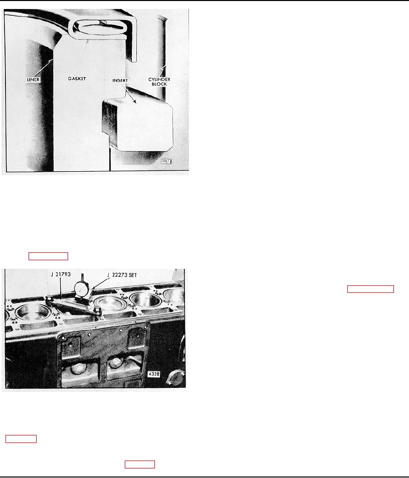
flange must be .045" to .050" below the surface of the
block. However, even though all of the liners are within
these specifications, there must not be over .002"
difference in depth between any two adjacent 'liners
when measured along the cylinder longitudinal center
line.
NOTE: A .002" thick shim is available for
adjusting the liner height (in the current " high"
block only). The shim must be installed
underneath the liner insert. Do not cut the
shim for installation. Liner inserts which are
.0015 " thicker or thinner than standard are
also available for service. In addition, the
.004" and .008"
thinner inserts (also
available in .0015" thicker and thinner sizes),
which are provided for use with re-surfaced
cylinder blocks, can also be used to adjust the
liner height.
6. Matchmark the liner and the cylinder block with chalk
Fig. 11 - Cylinder Liner Mounting in Block
or paint so the liner may be reinstalled in the same
position in the same block bore. The match-marks
3. Push the cylinder liner into the cylinder block until the
should be toward the blower side of the engine.
liner flange rests on the insert. Do not use excessive
force to install the liner. The liner should slide smoothly
7. Remove the hold-down clamp and the cylinder liner.
in place with thumb pressure. If a new liner cannot be
pushed in place, light honing of the block bore may be
NOTE: Do not remove the liner insert.
necessary to obtain the desired fit for best heat transfer.
Refer to Section 1.0 for the liner-to-block clearance.
Install Piston and Connecting Rod Assembly
1. With the piston assembled to the connecting rod and
the piston rings in place as outlined in Sections 1.6 and
1.6.1, apply Cindol 1705 oil to the piston, rings and the
inside surface of the piston ring compressor J 3272-02.
NOTE: Inspect the ring compressor for nicks
or burrs, especially at the non-tapered inside
diameter end. Nicks or burrs on the inside
diameter of the compressor will result in
damage to the piston rings.
2. Place the piston ring compressor on a wood block,
with the chamfered end of the ring compressor facing up.
3. Position (stagger) the piston ring gaps properly on
Fig. 12 - Checking Distance of Liner Flange
the piston. Make sure the ends of the oil control ring
Below Top Face of Block
expanders are not overlapped.
4. Install a cylinder liner hold-down clamp as illustrated
4. Start the top of the piston straight into the ring
in Fig. 12.
5. Measure the distance from the top of the liner to the
top of the block with a dial indicator (Fig. 12). The liner
Page 107

