
TM 5-3810-300-24&P-3
Fuel Injector
2.1.1
Each fuel injector has a circular disc pressed into a
recess at the front side of the injector body for
identification purposes (Fig. 5). The identification tag
indicates the nominal output of the injector in cubic
millimeters.
Each injector control rack (Fig. 2) is actuated by a lever
on the injector control tube which, in turn, is connected to
the governor by means of a fuel rod. These levers can
be adjusted independently on the control tube, thus
permitting a uniform setting of all injector racks.
Fig. 3 Fuel Metering from No-Load to Full-Load
The fuel injector combines in a single unit all of the parts
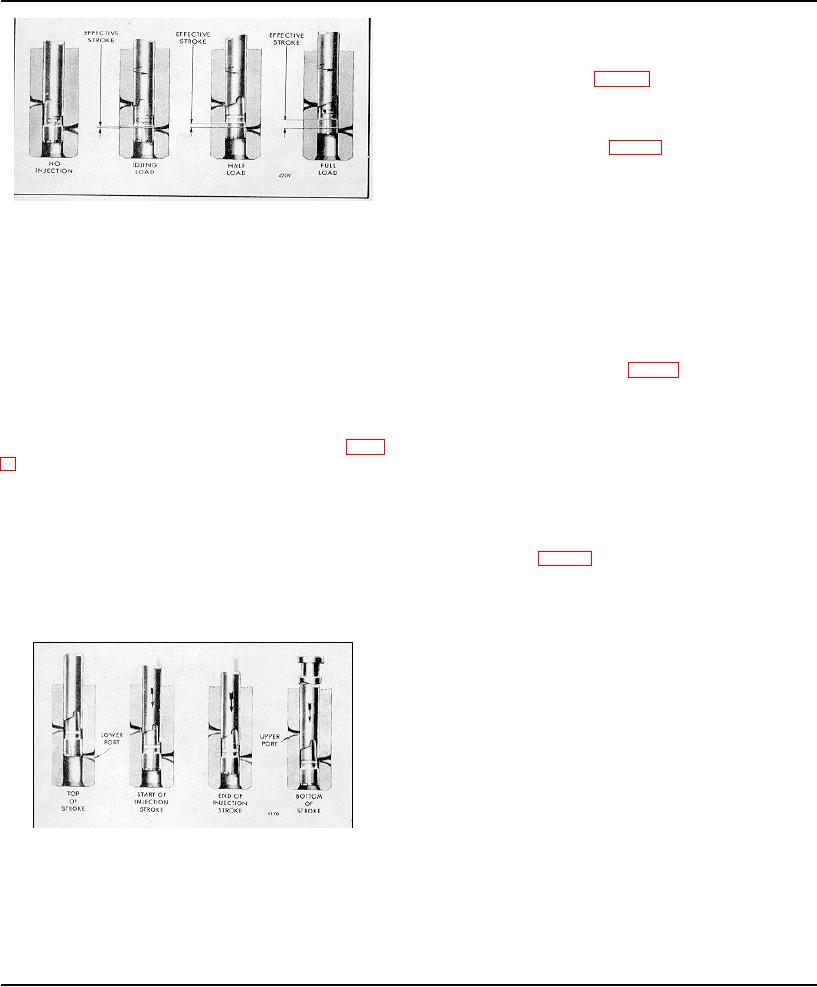
Figure 4 illustrates the phases of injector operation by
necessary to provide complete and independent fuel
the vertical travel of the injector plunger.
injection at each cylinder.
The continuous fuel flow through the injector serves, in
Operation
addition to preventing air pockets in the fuel system, as a
coolant for those injector parts subjected to high
Fuel, under pressure, enters the injector at the inlet side
combustion temperatures.
through a filter cap and filter (Fig. 2). From the filter, the
fuel passes through a drilled passage into the supply
To vary the power output of the engine, injectors having
chamber, that area between the plunger bushing and the
different fuel output capacities are used. The fuel output
spill deflector, in addition to that area under the injector
of the various injectors is governed by the helix angle of
plunger within the bushing. The plunger operates up and
the plunger and the type of spray tip used. Refer to Fig.
down in the bushing, the bore of which is open to the fuel
5 for the identification of the injectors and their respective
supply in the annular chamber by two funnel-shaped
plungers and spray tips.
ports in the plunger bushing.
Since the helix angle on the plunger determines the
The motion of the injector rocker arm is transmitted to
output and operating characteristics of a particular type
the plunger by the follower which bears against the
of injector, it is imperative that the correct injectors are
follower spring (Fig. 6). In addition to the reciprocating
used for each engine application. If injectors of different
motion, the plunger can be rotated, during operation,
types are mixed, erratic operation will result and may
around its axis by the gear which meshes with the control
cause serious damage to the engine or to the equipment
rack. For metering the fuel, an upper helix and a lower
which it powers.
helix are machined in the lower part of the plunger. The
relation of the helices to the two ports changes with the
rotation of the plunger.
As the plunger moves downward, under pressure of the
injector rocker arm, a portion of that fuel trapped under
the plunger is displaced into the supply chamber through
the lower port until the port is closed off by the lower end
of the plunger. A portion of the fuel trapped below the
plunger is then forced up through a central passage in
the plunger into the fuel metering recess and into the
supply chamber through the upper port until that port is
closed off by the upper helix of the plunger. 'With the
upper and lower ports both closed off, the remaining fuel
under the plunger is subjected to increased pressure by
Fig. 4 - Phases of Injector Operation Through Vertical
the continued downward movement of the plunger.
Travel of Plunger
When sufficient pressure is built up, it opens the flat,
CAUTION: Do not intermix the needle
valve injectors with other types of
injectors in an engine.
Page 158

