
TM 5-3810-300-24&P-3
Fuel Injector
2.1.1
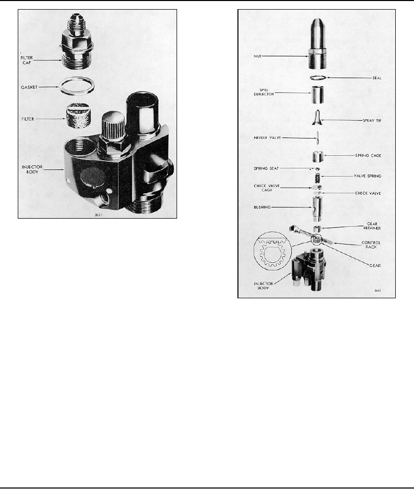
Fig. 35- Details of Injector Filters and Caps and Their
Relative Location
the plunger and bushing together as they are mated
parts.
After washing, submerge the parts in a clean receptacle
containing clean fuel oil. Keep the parts of each injector
assembly together.
Fig. 36 - Injector Rack, Gear, Spray Tip and Valve
Inspect Injector Parts
Assembly Details and Relative Location of Parts
Inspect the teeth on the control rack and the control rack
The current injector follower spring (.142" diameter wire)
gear for excessive wear or damage. Also check for
has a free length of approximately 1.504" and should be
excessive wear in the bore of the gear and inspect the
replaced when a load of less than 70 lbs. will compress
gear retainer. Replace damaged or worn parts.
it to 1.028"
Inspect the injector follower and pin for wear. Refer to
It is recommended that at the time of overhaul, all
Section 2.0.
injectors in an engine be converted to the current spring
(.142 "diameter wire) which will provide improved cam
Inspect both ends of the spill deflector for sharp edges or
roller to shaft follow. However, in the event that one or
burrs which could create burrs on the injector body or
two injectors are -changed, the remaining injectors need
injector nut and cause particles of metal to be introduced
not be reworked to incorporate the current spring.
into the spray tip and valve parts. Remove burrs with a
500 grit stone.
Check the seal ring area on the injector body for burrs
Inspect the follower spring for visual defects. Then
check the spring with spring tester J 9666 and an
accurate torque wrench.
Page 173

