
TM 5-3810-300-24&P-3
2.2
FUEL PUMP
Certain engine applications use a high-capacity fuel pump with
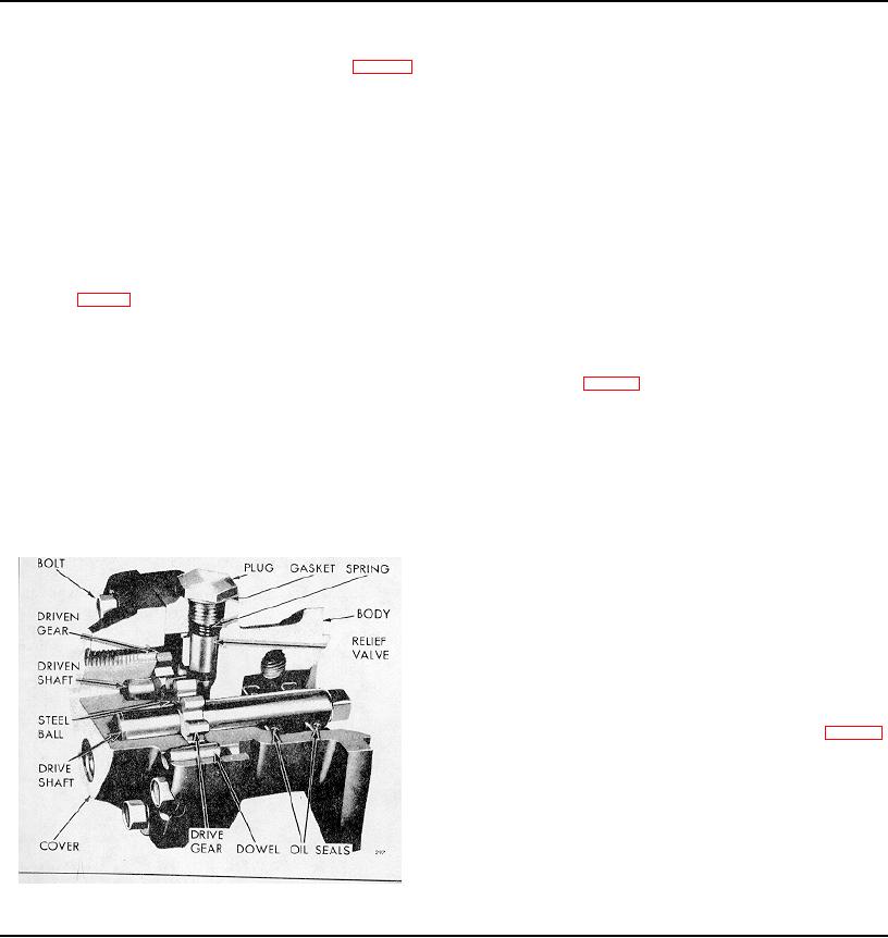
The positive displacement gear-type fuel pump (Fig. 1)
3/8 "wide gears to increase fuel flow and reduce fuel spill
transfers fuel from the supply tank to the fuel injectors. The
temperature. The high-capacity fuel pump and the standard
pump circulates an excess supply of fuel through the injectors
fuel pump with 1/4"wide gears are not completely
which purges the air from the system and cools the injectors.
interchangeable; therefore, when replacing a standard pump
The unused portion of fuel returns to the fuel tank by means of
with a high-capacity pump, the appropriate fuel lines and
a fuel return manifold and fuel return line.
connections must be used.
The fuel pump is attached to the rear end plate cover of the
The fuel pump cover and body are positioned by two dowels.
blower assembly with three bolt and seal assemblies. The
The dowels aid in maintaining gear shaft alignment. The
seals are flat, soft copper washers which prevent the oil in the
mating surfaces of the pump body and cover are perfectly flat
blower cover from seeping out around the bolt threads. The
ground surfaces. No gasket is used between the cover and
pump is driven off the end of the blower lower rotor by means
body since the pump clearances are set up on the basis of
of a drive coupling fork attached to the end of the pump drive
metal-to-metal contact. A very thin coat of sealant provides a
shaft and mating with a drive disc attached to the blower rotor
seal against any minute irregularities in the mating surfaces.
as shown in Fig. 2.
Cavities in the pump cover accommodate the ends of the drive
and driven shafts.
On certain applications, the fuel pump is attached to a special
flywheel housing large hole cover. It is driven off of the
The fuel pump body is recessed to provide running space for
balance shaft gear by means of a drive coupling fork attached
the pump gears (Fig. 3). Recesses are also provided at the
to the end of the pump drive shaft and mating with a drive
inlet and outlet positions of the gears. The small hole "A"
adapter bolted to the balance shaft gear.
permits the fuel oil in the inlet side of the pump to lubricate the
relief valve at its outer end and to eliminate the possibility of a
Fuel pumps are furnished in left-hand or right-hand rotation,
hydrostatic lock which would render the relief valve
according to the engine model, and are stamped "LH IN" or
inoperative. Pressurized fuel contacts the relief valve through
"RH IN". The left-hand pumps are used on LA-LB-RA-RB
hole "B" and provides for relief of excess discharge pressures.
engines while the right-hand pumps are used on LC-LD-RC-
Fuel re-enters the inlet side of the pump through hole "C"
RD engines. These pumps are not interchangeable, nor can a
when the discharge pressure is great enough to move the
pump made for one rotation be rebuilt for the other rotation
relief valve back from its seat. Part of the relief valve may be
since the relief valve can be installed in only one position in
seen through hole "C". The cavity "D" provides escape for the
the pump body.
fuel oil which is squeezed out of the gear teeth as they mesh
together on the discharge side of the pump. Otherwise, fuel
trapped at the root of the teeth would tend to force the gears
apart, resulting in undue wear on the gears, shafts, body and
cover.
Two oil seals are pressed into the bore in the flanged side of
the pump body to retain the fuel oil in the pump and the
lubricating oil in the blower timing gear compartment. The oil
seals are installed with the lips of the seals facing toward the
flanged end of the pump body. A small hole "E" (Fig. 3)
serves as a vent passageway in the body, between the inner
oil seal and the suction side of the pump, which prevents
building up any fuel oil pressure around the shaft ahead of the
inner seal.
Some fuel oil seepage by the fuel pump seals can be
expected, both with a running engine and immediately after an
engine has been shut down. This is especially true with a new
fuel pump and/or new pump seals, as the seals have not yet
conformed to the pump drive
Fig. 1 Typical Fuel Pump Assembly
Page 182

