
TM 5-3810-300-24&P-3
LIMITING SPEED GOVERNOR
2.7.1
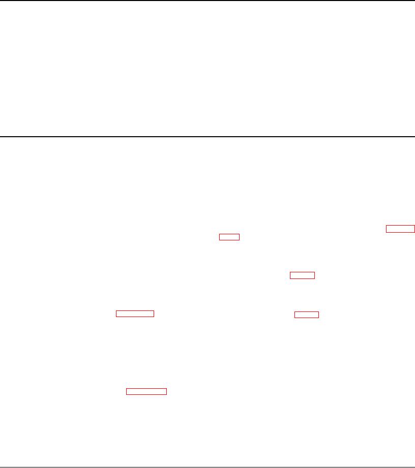
Fig. 1 - Limiting Speed Mechanical Governors
2. Housing--Governor
28. Screw--Gap Adjusting
50. Retainer--High Speed
66. Shaft Assy.--Weight
Control
29. Lock Nut
Spring
67. Riser--Governor
3. Cover--Governor
30. Bearing--Operating
51. Cover--High Speed
70. Bearing--Shaft End
5. Screw
Shaft
Spring Retainer
71. Bolt--Retaining
6. Lock Washer
40. Bushing--Operating
53. Bolt
73. Fork--Operating
12. Lever--Throttle Shaft
Shaft
55. Screw--Idle Speed
Shaft
14. Rod--Fuel
44. Plunger--High Speed
Adjusting
75. Carrier--Weight
17. Cam
Spring
56. Lock Nut
21. Lever--Speed Control
45. Seat--Low Speed Spring
57. Screw--Buffer
23. Lever--Differential
46. Spring--Low Speed
58. Lock Nut
82. Gasket
26. Shaft--Operating
47. Cap--Low Speed Spring
59. Housing--Weight
83. Plug--W7eight Housing
27. Lever--Operating
48. Spring--High Speed
60. Bearing--Riser Thrust
272. Weights--Low Speed
Shaft
49. Lock Nut--Retainer
273. Weights--High Speed
slinger attached to the lower rotor shaft, provides lubrication
Throughout the intermediate speed range the operator has
for the governor weights and weight carrier.
complete control of the engine because both the low speed
spring and the low speed weights are against their stops, and
Pressure lubrication has been provided for the weight housing
the high speed weights are not exerting enough force to
bearings on current engines by an oil tube attached between
overcome the high speed spring.
the oil gallery in the cylinder block and the governor weight
housing.
As the speed continues to increase, the centrifugal force of the
high speed weights increases until this force can overcome the
high speed spring and the governor again takes control of the
Remove Governor
engine, limiting the maximum engine speed.
Governor operation should be checked as outlined in Section
A fuel rod (14), connected to the differential lever and injector
2.7 before the governor is removed from the engine. If, after
control tube lever, provides a means for the governor to
performing these checks, the governor fails to control the
change the fuel settings of the injector control racks.
engine properly, it should be removed and reconditioned.
The engine idle speed is determined by the centrifugal force of
1. Disconnect the linkage attached to the governor
the low speed weights (272) required to balance out tension
control levers (Fig. 2).
on the low speed spring.
2. Remove the breather tube.
Adjustment of the engine idle speed is accomplished by
changing the tension on the low speed spring by means of the
3. Remove four screws and lock washers and lift the
idle adjusting screw (55). Refer to Section 14 for the idle
governor cover (Fig. 3) and gasket from the governor
speed adjustment.
housing.
The maximum no-load speed is determined by the centrifugal
4. Refer to Figs. 1 and 2 and disconnect the fuel rod
force of the high speed weights (273) required to balance out
from the differential lever (23) and the injector control
the tension on the high speed spring.
tube lever.
Adjustment of the maximum no-load speed is accomplished by
5. Disconnect the oil tube at the governor weight
the high speed spring retainer (50). Movement of the high
housing or cover and remove the cover, if used.
speed spring retainer nut will increase or decrease the tension
on the high speed spring. Refer to Section 14 for the
6. Remove the two governor-to-cylinder head bolts.
maximum no load speed adjustment.
7. Remove the control housing from the cylinder head
Lubrication
and weight housing.
8. Use tool J 4242, to remove the six governor, weight
Surplus oil returning from the cylinder head provides
housing-to-blower bolts; then withdraw the housing
lubrication for the parts in the governor control housing, the
from the blower.
riser thrust bearings, and the weight shaft end bearing. Oil,
picked up from a reservoir in the blower front end plate by a
Page 198

