
TM 5-3810-300-24&P-3
2.7.1
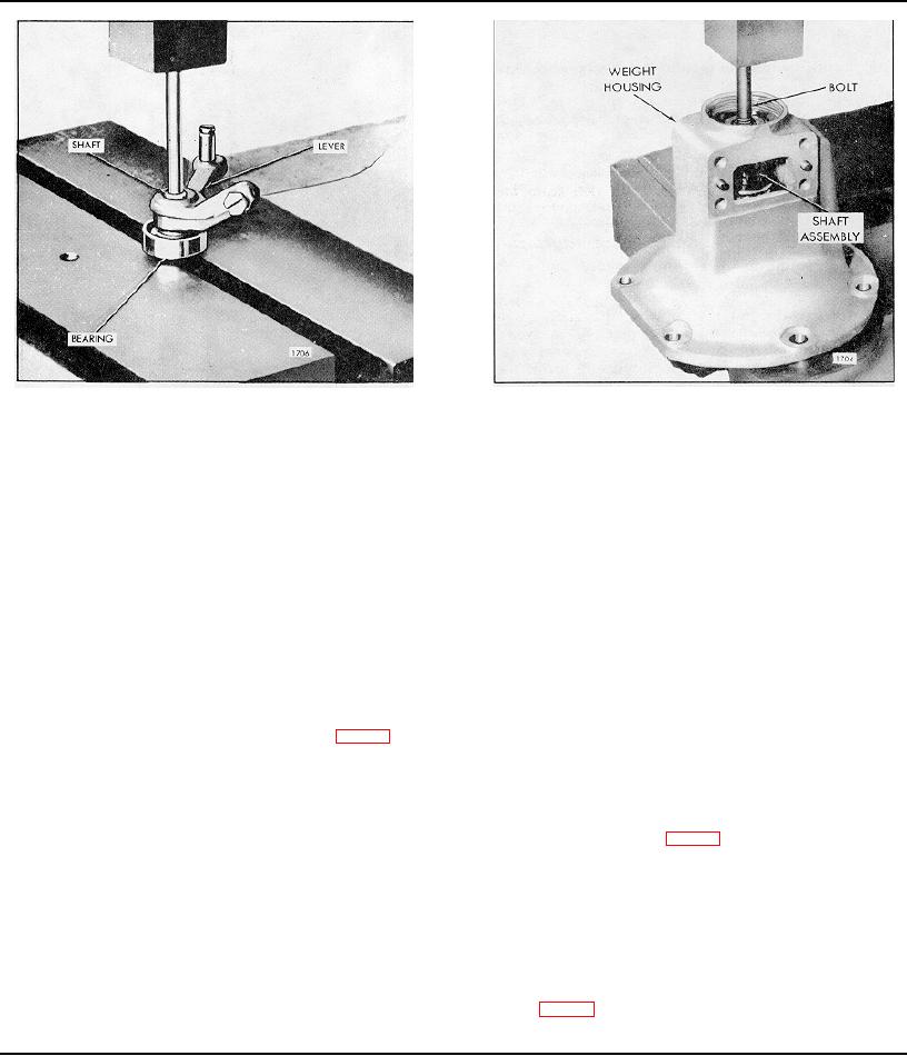
LIMITING SPEED GOVERNOR
Fig. 7 Removing Governor Weight and Shaft Assy.
Fig. 6 Removing Operating Shaft from Operating lever
Examine the governor or weights at the riser contact for
e.
Remove the bearing (70) from the weight
excessive wear. If this condition exists install a new governor
housing.
or weight.
f.
Mark the weights (76 or 272 and 273) and
Inspect the weight carriers, and retaining pins for wear.
carrier (75) with a center punch for
identification, also note position of the thin
Inspect the bushings in current weights and replace if worn
washers (78) between the weights so that the
excessively. In former weights inspect the needle bearings for
parts can be replaced in their original position.
wear and replace if necessary.
g.
Remove the Allen set screw (274) from the low
Inspect the operating shaft and bushing for excessive wear. If
speed weights.
Withdraw the pins and
excessive wear is noted, a new bushing and shaft must be
governor weights.
installed.
NOTE: If necessary the needle bearing in
Assemble Governor Cover
the high speed weights may be removed at
this time.
1. If the needle bearings were removed from the
governor cover, place the governor cover on the bed
h.
If required, the weight carrier (75), Fig. 9, may
of an arbor press with inner face of the cover down.
be pressed from the governor weight shaft and
Start the upper bearing straight into the bearing bore
a new carrier installed.
of the cover with the number on the bearing up.
Insert the bearing installer J 21068 in the bearing and
Inspection
press the bearing in until the shoulder on the tool
contacts the cover (Fig. 8).
Clean all of the parts with fuel oil, and dry them with
compressed air.
2. Turn the cover over and start the second bearing,
number side up, in the bearing bore. Press the
Revolve the ball bearings slowly by hand. Replace bearings
bearing in flush with the cover with tool J 21068.
which indicate rough or tight spots. Also replace bearings
which are corroded or pitted.
NOTE: Do not use impact tools to install
needle bearings.
Examine the riser thrust bearings for excessive wear, flat
spots, or corrosion. If any of these conditions exist, install a
3. Apply lubricant to the retaining pin and place the cam
new riser and bearing assembly.
(Fig. 3) over the pin with the boss of the cam up.
Install the stop lever.
Page 201

