
TM 5-3810-300-24&P-3
LIMITING SPEED GOVERNOR 2.7.1.1
5.
Slide the high speed spring and high speed
adjusting screw over the high speed spring plunger.
6.
Hold the assembly while positioning it in the control
housing, with the high speed spring plunger against
the support in the housing. Thread the high speed
spring adjusting screw into the housing sufficiently
to retain the assembly.
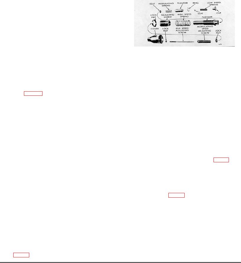
7.
Thread the high speed adjusting screw into the
Fig. 6 - Governor Springs, Plungers and Adjusting
housing until the end of the screw is approximately
Screws (Fuel Modulating Governor)
3/4" from the spanner lock nut.
Thread the
modulating spring adjusting screw in until the end of
3.
Assemble the riser thrust bearing on the weight
the screw is approximately 1 1/2" from the spanner
shaft with the bearing race with the smallest inside
lock nut.
diameter against the thrust riser.
Incorrect
installation of the bearing will result in erratic
Assemble Governor Weight Housing
operation of the governor.
1.
Refer to Fig. 4 and start the pin through the
4.
Insert the weight carrier and shaft assembly in the
opening in the weight carrier.
weight housing.
Place the low speed weight on the pin and slide the
5.
Support the splined end of the shaft on the bed of
pin through.
an arbor press. Start the shaft end bearing in the
housing and over the end of the shaft with the
Place two flat washers on the pin next to the low
numbered side of the bearing facing away from the
speed weights.
shaft. Press the bearing in place with a sleeve that
bears against the inner race.
Install the high speed weights on their shafts after
installing the needle bearings or bushings.
CAUTION: This bearing has thrust capacity
Place the high speed weight on the pin and slide the
in one direction only. Be sure to install the
pin through the weight.
bearing so that the thrust shoulder (Fig. 7) is
toward the governor weights. Otherwise, the
Place two more flat washers on the pin between the
force exerted by the weights will pull the
high speed weights and the carrier. Slide the pin
inner race and ball assembly away from the
through the washers and into the carrier.
outer race and result in damage to the
bearing and erratic governor operation.
Align the indentation in the pin with the set screw
hole in the low speed weights. Apply a sealant such
6.
Place the washer, Fig. 4, over the bearing retaining
as Loctite grade C or CV or equivalent on the
bolt. Thread the bolt into the tapped end of the
threads of the set screw Insert the set screw and
shaft and tighten it. Bend the tang on the washer
tighten it to 20 lb-in minimum. Be sure to stake the
against the head of the bolt.
set screw in two places after tightening the screws.
7.
Place a gasket in the housing, against the bearing.
NOTE:
Before applying the sealant to a
Apply a Loctite sealant grade HV or equivalent to
new set screw immerse the set screw i n
the full 360' circumference of the plug and thread
Loctite P rim e r T or equivalent.
the plug into the tapped end of the governor weight
housing. Tighten the plug to 45 lb-ft torque with
2.
Slide the riser over the shaft and against the
either flat or point of head on a horizontal line.
finished surfaces of the governor weights as shown
in Fig. 4.
Page 213

