
TM 5-3810-300-24&P-3
2.7.1.1 LIMITING SPEED GOVERNOR
After the control housing is installed, remove the bolt and
install the oil tube fitting.
6.
Affix a new gasket to the governor control housing,
then attach the governor control housing to the
cylinder head with two bolts. Tighten the bolts.
7.
Tighten the governor-to-blower bolts with wrench J
4242.
8.
Affix a new gasket to the weight housing cover
(former governors only) and place the cover in
position. Install the four weight housing-to-control
housing bolts with lock washers and tighten the
bolts.
9.
Connect the oil tube to the fitting on the weight
housing or on the cover (if used).
10.
Position the fuel rod (14) over the differential lever
Fig. 7 - Governor Weight Shaft Bearing
pin (Fig. 1 in Section 2.7.1). Place a flat washer
over the pin and secure it with the retainer (25).
Install Governor
11.
Attach the fuel rod to the injector control tube lever
with a pin and cotter pin.
1.
Affix a new gasket, (Fig. 4) to the governor weight
12.
Place a new gasket (4), Fig. 1, on the governor
housing. Start the splined end of the weight shaft in
control housing and mount the governor cover on
the upper blower rotor and position the housing
the housing with the pin on the throttle shaft (7)
against the blower end plate.
registering with the machined slot in the differential
lever (23).
2.
Place a new copper gasket on each weight
13.
Install the four cover screws (5) with lock washers.
housing-to-blower bolt and thread the bolts into the
One end of the cam spring (20) is anchored to one
blower end plate, finger tight only.
of the cover screws (Fig. 2).
3.
Place a new gasket (Fig. 4) over the dowels and
14.
Connect throttle linkage.
against the side of the weight housing facing the
15.
Attach the breather tube to the governor housing.
engine.
16.
Tune-up the engine as outlined in Section 14.5.
4.
Move the thrust bearing assembly and riser toward
the weight end of the shaft.
5.
Position the lower end of the control housing over
the dowel pins in the weight housing.
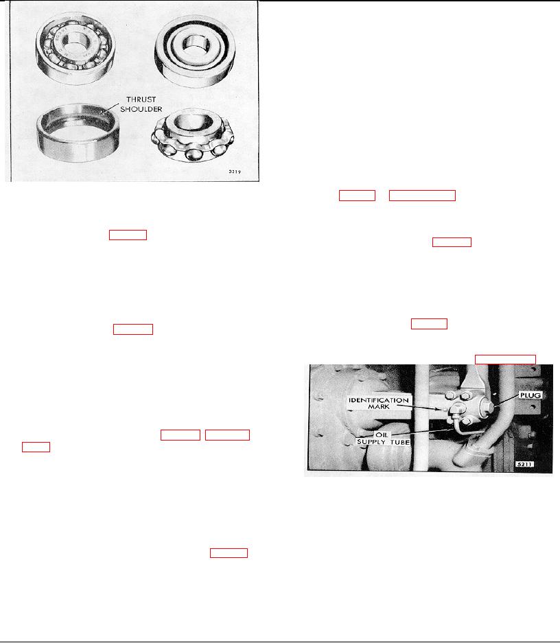
NOTE 1: The finished surface of the operating
fork must be placed against the outer side of the
NOTE 2: Current weight housings have two ribs
cast on the inner surface of the housing to
Fig. 8-Governor Weight Housing
prevent any part of the riser thrust bearing from
sliding forward to where the operating fork could
be inserted on the wrong side of one or more
parts of the bearing. For ease in assembling
the governor control housing to the interim
weight housings (no identification mark), Fig. 8,
place a 3/8"-24 x 3/4" or 7/8" bolt, from which the
outer 1/2" of thread down to a diameter of 5/16"
to 1/4" has been removed, in the 1/8" NPIYF oil
hole to prevent the thrust bearing from moving
too far forward in the weight housing.
Page 214

