
TM 5-3810-300-24&P-3
2.7.1.3 Variable-Speed Limiting Speed Governor
Inspect Governor Parts
Wash all of the parts in clean fuel oil and dry them with
compressed air, then inspect them as outlined in Section
Assemble Governor
NOTE: During assembly, lubricate all spring
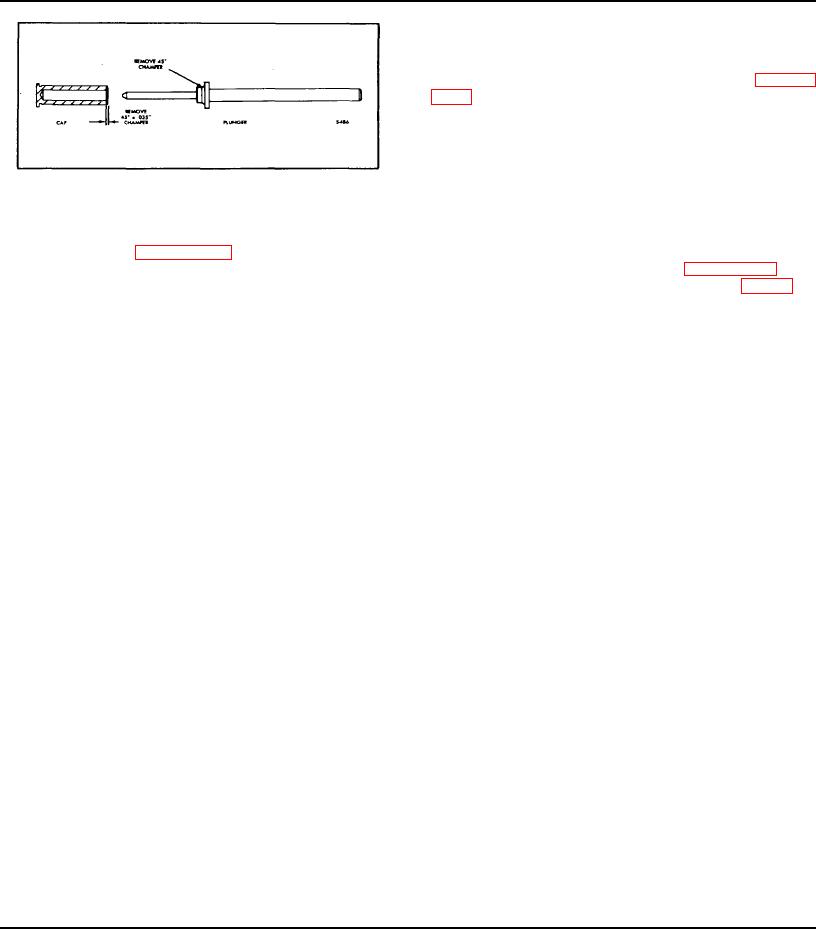
Fig. 2 - Rework Former Plunger and Cap
housing components and needle bearing
assemblies with MIL. G3278A, Aero Shell 7A
grease, or equivalent (special grease for high
exception of the spring housing and its
and low temperature operations).
components. Therefore, disassemble the governor
as outlined in Section 2.7.1, then disassemble the
Assemble the governor as outlined in Section 2.7.1, then
spring housing and its components (Fig. I) as
assemble the spring housing and components (Fig. 1).
follows:
To assure a 550 rpm idle speed for certain on highway
1.
Clamp the flange of the governor housing in a vise
vehicle engines, the spring seat chamfer has been
equipped with soft jaws.
removed from the low-speed spring plunger and cap.
The internal chamfer has been removed from both ends
2.
Remove the two bolts and lock washers securing
of the coil of the outer low-speed spring. A high idle
the spring housing to the governor housing and
condition could be the result if an unchamfered spring
withdraw the spring housing and gasket.
did not seat properly due to the chamfer on the former
plunger and cap. To correct this condition, install a
3.
Remove the adjusting coupling from the adjusting
current (modified) plunger and cap, or remove the 45
shaft.
chamfer from the spring seat area of the plunger and
also the 45 x .035 " chamfer on the cap (shaded area,
4.
Hold the adjusting lock nut with a wrench and back
Fig. 2).
off the retainer and adjusting shaft.
5.
Unscrew the adjusting shaft from the retainer.
CAUTION: A chamfered spring should not be
used with an unchamfered plunger and cap,
6.
Unscrew the idle speed adjusting lock nut from the
because a severe wear condition will result.
end of the high-speed spring plunger.
1.
Thread the spring retainer lock nut on the high-
speed spring retainer approximately 1-1/2 ".
7.
Unscrew the high-speed spring retainer lock nut
2.
Place the high-speed spring on the high-speed
and remove the high-speed spring retainer, plunger
spring plunger.
and spring along with the low-speed spring plunger,
3.
Insert the high-speed spring and plunger assembly
inner and outer springs and low-speed spring cap
in the high-speed spring retainer.
as an assembly from the governor housing.
4.
Insert the low-speed spring plunger into the high-
speed spring plunger.
8.
Remove the high-speed spring retainer and spacer
5.
Place the inner and outer springs in the lower end
assembly and spring from the high-speed spring
of the high-speed spring plunger, over the low-
plunger. Remove the low-speed spring cap from
speed spring plunger.
the opposite end of the high-speed spring plunger
6.
Install the low-speed spring cap over the end of the
and remove the low-speed spring plunger along
inner low-speed spring and into the end of the high-
with the inner and outer low-speed springs.
speed spring plunger and install the assembly in the
governor housing.
NOTE: The high-speed spring retainer on early
CAUTION: Place the spring housing gasket in
engines did not include a spacer. If the shaft
position before installing the assembly.
sticks in the retainer, replace it with the current
retainer and spacer assembly.
Page 223

