
TM 5-3810-300-24&P-3
OIL PUMP 4.1
1. Hold the pump assembly against the main
bearing caps so the idler gear (56) meshes with
the driving gear on the crankshaft.
2. Insert the four bolts (55) with lock washers
through the mounting feet of the pump and into
the bearing caps (39). Align the pump so that
the teeth of crankshaft gear and the idler gear
are parallel; then tighten the bolts to 35-39 lb-ft
cast iron cylinder block and check clearance
between gear teeth with a feeler gage. Proper
clearance between crankshaft gear and idler
gear is .005" minimum, .012" maximum (Fig.
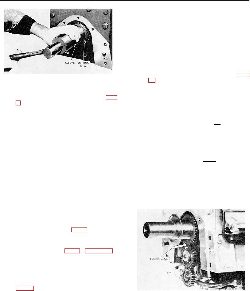
Fig. 9. Installing Oil Pump Driving Gear on Crankshaft
2. Remove the oil slinger.
CAUTION: Always check the clearance
between the crankshaft gear and the oil
3. If required use puller J 3051, as illustrated in Fig.
pump idler gear with the engine in the
8 to pull the pump driving gear from the front end
upright or running position.
of the crankshaft as follows:
If shims were used between the pump mounting feet and
a. Screw crankshaft pulley or cap retaining
the bearing caps and new gears are not installed, the
bolt into the end of the crankshaft.
same shims (cleaned) or the same number of new
(identical) shims should be installed and the number then
b. Attach the jaws of the puller behind the
adjusted to obtain the proper clearance between gear
gear and locate the point of puller screw in
teeth. However, if new gears have been installed, a
the center of the retaining bolt.
larger number of shims will be required under the
mounting feet. In either event, the pump must be
c. Turn the puller screw clockwise and draw
tightened on the bearing cap before the clearance
the gear from the crankshaft.
between the gear teeth is measured.
4. Remove the Woodruff key from the crankshaft.
NOTE: When adjusting for gear tooth
clearance by installing or removing
Install Oil Pump Driving Gear on Crankshaft
shims, the same number of shims must
be changed under each foot so that the
1. Install the Woodruff key in the crankshaft.
pump will always be level on the main
bearing caps. The insertion or removal
2. Position the gear (80) so the chamfer on the
gear hub is toward the main bearing cap and
start the gear on the shaft and over the key.
3. Slide the gear on the crankshaft or use a sleeve
if required, as illustrated in Fig. 9, and drive the
gear tight against the shoulder on the crankshaft.
4. Install the oil slinger with dished side away from
the gear as illustrated in Fig. 1 in Section 1.3.6.
5. Install the crankshaft front cover as outlined in
Section 1.3.5.
Install Oil Pump
Refer to Fig. 2 and install the oil pump on the main
Fig. 10. Measuring the Clearance Between the Teeth
bearing caps as follows:
of the Oil Pump Driven Gears
PAGE 287

