
TM 5-3810-300-24&P-3
6
SECTION 6
EXHAUST SYSTEM
CONTENTS
Exhaust Manifold .........................................................................................
EXHAUST MANIFOLD
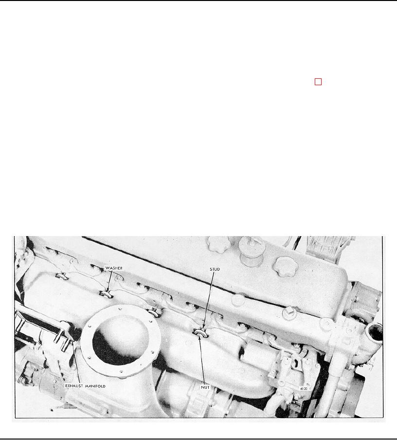
An air-cooled exhaust manifold (Fig. I) is attached to
to prevent entry of foreign material. Then remove the air
the cylinder head. The location and angle of the exhaust
compressor (if used) and the governor control housing.
outlet of the manifold varies with the engine model. The
3. Remove the nuts, bevel washers and end crabs that
exhaust manifold is secured to studs, located between
attach the exhaust manifold to the cylinder head. It is
the exhaust ports and at the outer sides of the end ports
suggested that, as a safety measure, the nut be
of the cylinder head, with bevel washers and nuts. A
loosened but left on the center stud until all of the other
exhaust manifold three-piece gasket is used on the 6-71
nuts and washers have been removed.
engine.
4. Support the manifold and remove the nut and
washer from the center stud.
5. Lift the manifold away from the cylinder head.
Remove Exhaust Manifold
6. Remove the manifold gaskets.
1. Disconnect the exhaust pipe from the exhaust
manifold.
2. If the exhaust manifold is mounted on the blower
side of the engine (Fig. 1), remove the air inlet housing
from the blower.
Cover the air inlet opening
Fig. 1. - Typical Exhaust Manifold Mounting
Page 325

