
TM 5-3810-300-24&P-3
7.3.1
A solenoid switch is included in the starting system on a
Series 71 engine using a Bendix drive starter to provide
a means of opening and closing the circuit between the
starting motor and the battery during the cranking
operation. The switch is mounted on a plate which in
turn may be mounted on or near the starting motor.
Specifications of a typical starting switch are as follows:
"Pull-In" Voltage potential of 15 volts, plus or minus one
volt, is required to pull the plunger into operating position.
"Hold-In" Voltage potential of not less than 3.5 volts is
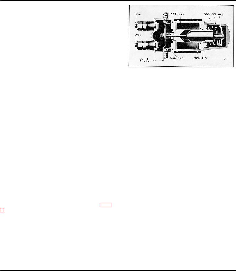
Fig. 1 - Typical Solenoid Switch Assembly
required to hold the plunger in its opening position.
373
Coil
378 Stud--Terminal
374
Plunger and Rod
379 Stud--Starting Motor
Resistance of Solenoid Winding is from 3.8 to 4.0 ohms.
Assy Cable Terminal
375
Disc--Contact
380 Spring--Plunger
Four terminals are provided on the switch, two of which
Return
are at the lower end for the connection of the battery and
376
Stud--Battery Cable
381 Cover--Plunger
motor leads. Two smaller terminals, one on each side of
Terminal
413 Cup--Plunger
the switch, are provided for the connection of the lead
Spring
from the starting switch on the instrument panel and the
377
Stud--Terminal
416 Gasket--Plunger
lead from the fuse which is grounded to the engine base.
Cover
Insulating bushings and washers are used to completely
insulate the terminals from the switch body.
(379), the circuit between the motor and battery is
The starting motor-battery circuit is opened and closed
completed and the cranking operation begins.
inside the switch body by means of a contact disc
(circular plate) which is attached to, but insulated from, a
The cranking operation continues until the circuit is
plunger which is free to move up or down within the
broken by releasing the starting switch on the instrument
body. When in the non-operating position, the contact
panel. When this happens, the circuit through the coil is
disc is held away from the terminals by the tension of a
broken and the magnetic field collapses. This allows the
spring, bearing against a cap attached to the upper end
return spring (380) to pull the plunger out of the coil core
of the plunger.
and the contact disc away from the battery and starting
motor (studs) contacts.
Operation
Starting Cautions
1. Press starting button firmly.
When the instrument panel starting switch contacts are
2. If the engine fails to start after first attempt, do not
closed, a circuit is completed across the solenoid switch
press starting button again until engine has stopped
terminals (377) and (378) and through the coil (373), Fig.
rotating.
1. The resultant magnetic field created in the core of the
coil overcomes the tension of the return spring (380),
Serious damage may result to the starting motor if the
Fig. 1, and the plunger (374) is drawn downward into the
above rules are not followed.
magnetic field, carrying the contact disc (375) with it.
When the contact disc touches the contacts (376) and
Periodically, inspect all terminals
to
make
sure
connections are clean and tight.
Remove Solenoid Switch
1. Disconnect the battery cable and the starter switch
wire from the terminal stud (376), also disconnect
starting motor cable from terminal stud (379).
Page 344

