
TM 5-3810-300-24&P-3
14.3 LIMITING SPEED GOVERNOR ADJUSTMENT
Relocate the fuel modulator lever and roller
assembly in its original position opposite the cam so
the cam is centrally located on the roller. Tighten
the "U" bolt nuts until the lever and roller assembly
is snug on the control tube. This will not only permit
the adjustment of the lever, but will retain the
adjustment until the roller and lever assembly can
be securely tightened.
2
Hold the fuel modulating piston and cam in the high
speed position by applying not less than 20 psi air
pressure to the piston or by prying the cam out with
a screw driver.
3
Hold the injector rack in the full-fuel position.
4
While holding the cam and the injector rack, move
the fuel modulating lever and roller assembly until
the roller contacts the cam. Carefully tighten the
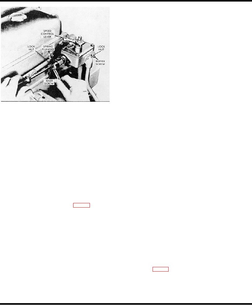
Fig. 7 - Adjusting Engine Idle Speed
clamping nuts on the "U" bolt alternately to avoid
changing the position of the roller against the cam.
1
With the engine stopped, remove the two attaching
bolts and withdraw the governor high speed spring
Check Fuel Modulator Setting
retainer cover.
1
Pry the fuel modulating cam out with a screw driver.
The recommended idle speed is 550 rpm for single
weight governors and 450 rpm for double weight
2
Move the injector control tube to the full-fuel
governors, but may vary with engine applications.
position.
3
Hold the idle screw and tighten the lock nut.
3
Release the pressure on the screw driver slightly
and allow the cam to move in slightly. If properly
4
Install the high speed spring retainer and retain with
set, the roller of the fuel modulating lever and roller
the two bolts.
assembly will rotate as soon as the cam moves.
Repeat this check several times to ensure the
Adjust Buffer Screw
proper setting was not disturbed while tightening the
"U" bolt clamping nuts.
With the idle speed set, adjust the buffer screw as
follows: 1. With the engine running at normal operating
Adjust Fuel Shut-Off Air Cylinder Linkage Engines
temperature, turn the buffer screw (Fig. 7) in so that it
contacts the differential lever as lightly as possible and
With Fuel Shut-Off Cylinder Assembly ter completing the
still eliminates the engine roll.
adjustment of the engine governor, adjust the linkage
between the air shut-off cylinder and the injector fuel
NOTE: Do not increase the engine idle
control tube lever according to the following procedure.
speed more than 15 rpm with the buffer
screw.
1
Place the governor control lever into the full speed
position. The movement of the control lever to the
2
Hold the buffer screw and tighten the lock nut.
full-speed position will move the injector racks to
the full-fuel position.
3
Recheck the maximum no-load speed. If it has
increased more than 25 rpm, back off the buffer
2
Loosen the lock nuts on the air cylinder fuel shut-off
screw until the increase is less than 25 rpm.
rod (Fig 9) and lengthen the rod by turning the
turnbuckle until the end of the slot contacts the pin
Adjust Fuel Modulator-Engines With Fuel Modulator
in the end of the control tube shut-off lever. Then
shorten the rod one complete turn of the turnbuckle
After adjusting of the engine governor. adjust the Fuel
and tighten the lock nuts.
modulator trig. 0), 11 the engine is so equipped,
according to the following procedure.
Page 391

