
TM 5-3810-300-24&P-3
14.3.2
LIMITING SPEED MECHANICAL GOVERNOR (DUAL RANGE) AND INJECTOR RACK CONTROL ADJUSTMENT
Adjust the limiting speed mechanical governor (dual
range) and injector rack control levers after adjusting the
exhaust valves and timing the fuel injectors.
Loosen the lever and disconnect the air cylinder link (if
used), before proceeding with the governor adjustment.
Adjust Governor Gap
With the engine at operating temperature, adjust the
governor gap as follows:
1
With the engine stopped, remove the two attaching
bolts and withdraw the governor high speed spring
retainer cover.
2
Back out the buffer screw until it extends
approximately 5/8" from the lock nut (Fig 2).
3
Start the engine and loosen the idle speed adjusting
screw lock nut and adjust the idle screw to obtain
Fig. 2 - Positioning No. 1 Injector Rack Control Lever
the desired idle speed (Fig 1). Hold the screw and
tighten the lock nut to retain the adjustment The
5
Remove the valve rocker cover.
recommended idle speed is 450 rpm, but may vary
with special engine applications.
6
Remove the fuel rod from the differential lever and
the injector control tube lever.
4
Stop the engine and remove the governor cover
and lever assembly.
7
Start and run the engine between 800 and 1000
rpm by manual operation of the control tube lever.
CAUTION:
Do
not
overspeed
the
engine.
8
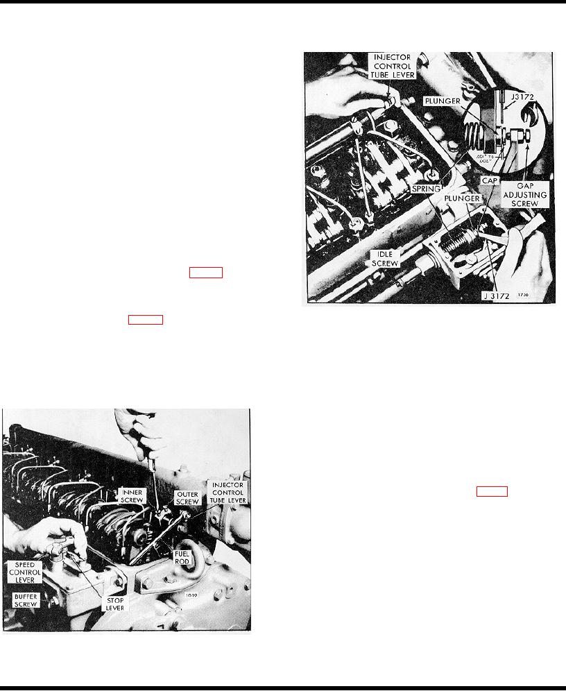
Check the gap between the low speed spring cap
and the high speed plunger with a .0015" feeler
gage tool J 3172 as shown in Fig 1. If the gap
setting is incorrect, loosen the lock nut and adjust
the gap adjusting screw.
9
Hold the gap adjusting screw and tighten the lock
nut.
10
Recheck the governor gap, with the engine
operating between 800 and 1000 rpm, by placing a
screw driver between the gap adjusting screw and
the governor housing and manually forcing the gap
closed.
If the setting is correct, the .0015"
movement can be seen by placing a few drops of oil
Figure 1 - Adjusting governor Cap
into the governor gap and pressing a screw driver
against the gap adjusting screw. Movement of the
cap toward the plunger will force the oil from the
gap in the form of a small bead.
Page 394

