
TM 5-3810-300-24&P-3
14.3.2 LIMITING SPEED GOVERNOR ADJUSTMENT (DUEL RANGE)
The setting is too tight if, when moving the speed
control lever from the idle to the maximum speed
position, the injector rack becomes tight before the
speed control lever reaches the end of its travel (as
determined by the stop under the governor cover).
This will result in a step up in effort required to
move the speed control lever to the end of its travel.
To correct this condition, back off the inner
adjusting screw slightly and tighten the outer
adjusting screw slightly.
6
Disconnect the fuel rod from the injector control
tube and manually hold the No 1 injector in the full-
fuel position and turn down the inner adjusting
screw of the No 2 injector until the injector rack has
moved into the full-fuel position and the inner
adjusting screw is bottomed on the injector control
tube. Turn the outer adjusting screw down until it
bottoms lightly on the injector control tube. Then,
alternately tighten both the inner and outer adjusting
screws.
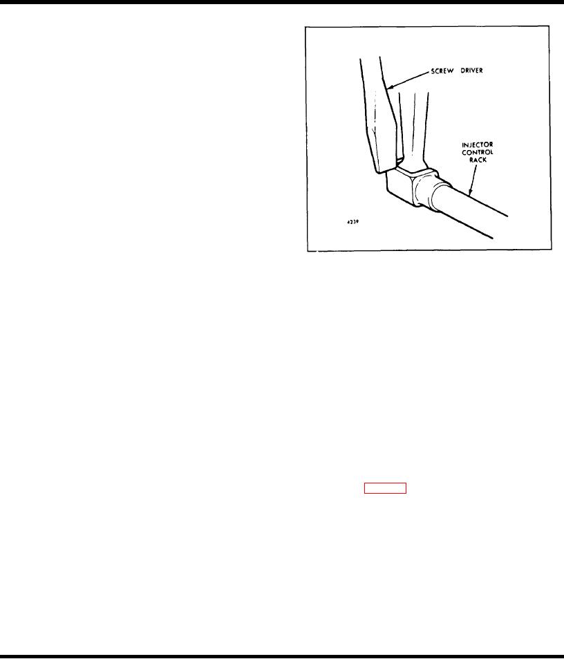
Fig. 4 - Checking Injector Control Rack "Spring"
7
Recheck the No 1 injector rack to be sure that. it
speed as given on the unit name plate, the maximum no-
has remained snug on the ball end of the injector
load speed may be set as follows: Engines with Early
rack control lever while adjusting the No 2 injector.
Dual Range Limiting Speed Mechanical Governor After
If the rack of the No 1 injector has become loose,
positioning the injector rack control levers and setting the
back off slightly on the inner adjusting screw on the
idle speed, set the maximum engine speeds.
No 2 injector rack control lever and tighten the outer
adjusting screw.
NOTE1: Be sure the buffer screw
projects 5/8" from the lock nut to prevent
When the settings are correct, the racks of both
its interference while adjusting the
injectors must be snug on the ball end of their
maximum no-load speeds.
respective rack control levers.
NOTE2: To prevent air leakage between
8
Position the remaining injector rack control levers
the piston and sleeve assembly, coat the
as outlined in Steps 6 and 7.
mating threads with sealant.
9
Connect the fuel rod to the injector control tube
With the spring housing assembly mounted on the
lever.
governor, the piston and sleeve assembly assembled as
illustrated in Fig. 5, and the low maximum speed
10
Reset the idle speed adjusting screw until it projects
adjusting screw extended from the spring housing
3/16" from the lock nut to permit starting the engine.
approximately 3/4" beyond the lock nut, proceed as
follows:
NOTE: Remove the "C" clamp from the
fuel rod on units having a yield link
CAUTION: Do not apply air pressure to the governor
until performing Step1h.
Adjust Maximum No-Load Engine Speed
1
Set the high maximum no-load speed.
All governors are properly adjusted before
leaving the factory. However, if the governor has
a Start the engine and place the speed control
been reconditioned or replaced, and to ensure
lever in the maximum speed position.
the engine speed will not exceed the
recommended no-load
Page 396

