
TM 5-3810-300-24&P-3
14.5 FUEL MODULATING GOVERNOR ADJUSTMENT
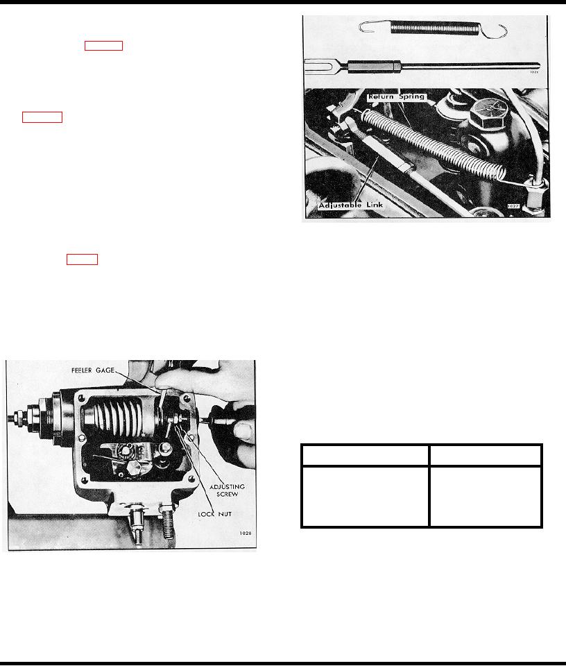
controlled by hand or temporary
adjustable link and spring at control
lever tube, Fig. 4.
Adjustment No. 2
Check the gap between the low speed spring cap (61)
and modulating spring plunger (57) with a .0015" feeler
gage, Fig. 5.
If the gap is not within .001"-.002" at 600-700 rpm,
loosen the lock nut (62) and turn the low speed gap
adjusting screw (63) as necessary to obtain the proper
gap. Tighten the lock nut (62) and recheck the gap.
No. 3-Checking Fuel Modulating Gap Closing
Preliminary Adjustment
Fig. 5 Low Speed Spring Gap Adjustment
A
If an adjustable link has been used, it should be
C
Start the engine and control the speed manually by
removed, Fig 4.
exerting force against the torsion spring (36) with a
finger.
B
Install the control link between the differential lever
and injector control tube lever
The
link
is
CAUTION: Care must be exercised to
secured at the governor end with a flat washer and
avoid overspeeding the engine.
retaining spring pin A straight pin and cotter pins are
used at the control tube. The link must be free with
Adjustment No. 3
no bind.
Advance the engine speed gradually until the low speed
spring cap (61) contacts the high speed plunger (39). Do
not exceed 2100 rpm. The gap closing speed should be
checked with a .0015" feeler gage between the mating
surface of (61) and (39), and will vary according to the
following table:
Fuel Modulator Spring Chart
F. M Spring
Closing Speed Range
225#/inch-WH ITE
1950-2040
175#/inch-GREEN
1850-1940
150#/inch-BROWN
1750-1840
70#/inch-YELLOW
1525-1625
If the closing speed does not fall within the correct range,
then recheck setting No. 1 or preliminary "B" to setting
No. 2 or check for the correct fuel modulating spring.
Fig. 4 Injector Rack with Adjustable Link and Spring
Installed
If, after rechecking the adjustments as indicated above,
the closing speed still does not fall within the specified
range, the modulating spring should be replaced.
No. 4-Fuel Modulating Cam Setting
Preliminary Adjustment
A Stop the engine.
Page 407

