
CONTROL VALVES
SUBSECTION 5C
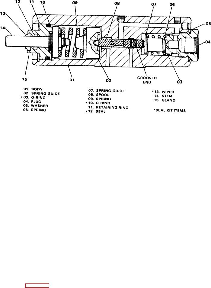
Figure 5C-8. Pressure Regulating Valve (36U258)
3. Place the valve assembly into the mounting bracket and
2. Perform the GENERAL REMOVAL procedures as found
attach support plates (18 and 30) to pedal (16) with pin (10),
in the beginning of this subsection.
washers (09), and cotter pins (11).
3. Disconnect and tag the hydraulic lines to the valve.
4. Assemble washers (02), spacer (04), spring (03) and nut
4. Remove the hardware holding the valve in place.
(01) to rod (05).
5. Remove the valve.
5. Connect the support plates to the brake valve stem with
pin (29), washers (19) and cotter pins (28).
6. Attach the hydraulic lines to the valve and valve block.
INSTALLATION AND ADJUSTMENT. To install and adjust
7. Start the engine and operate the brake pedal. Observe
the linkage to the third drum control valves, proceed as
the valve for leakage, binding or other problems.
follows:
8. Adjust the linkage as described in the Adjustment topic
for brake valve (36U259).
1. Attach the valve(s) with the capscrews, lockwashers and
nuts.
THIRD DRUM CONTROL VALVE (36Q372)
DESCRIPTION. Mounted below the third drum control con-
2. Connect the hydraulic lines to the fittings.
sole are two pressure reducing valves that control the third
3. Check and adjust the connecting rod to the 2-1/4" and
drum circuit. As the third drum control lever is moved for-
14" dimension shown in Figure 5C-9.
ward or back, hydraulic pressure is metered through these
4. Check and adjust for an air gap between the spherical
valves to actuate the third drum brake or clutch cylinders.
capscrews and the valve stems. This distance should be
The third drum control valves are not repairable. If it is
0.001". Secure the bolt with the jam nut.
determined that the valves are defective or leak excessively,
5. Connect the battery ground cable and start the engine.
they must be replaced.
6. Operate the third drum control lever to check for proper
REMOVAL. To remove the third drum control valve(s), pro-
operation of the valves. Check the valve stem area and all
ceed as follows (see Figure 5C-9):
hydraulic lines for leaks.
1. Remove the sheet metal cover directly below the console
7. Install the sheet metal cover over the valves.
cover.
5C-9

