
HYDRAULIC COMPONENTS
SUBSECTION 5D
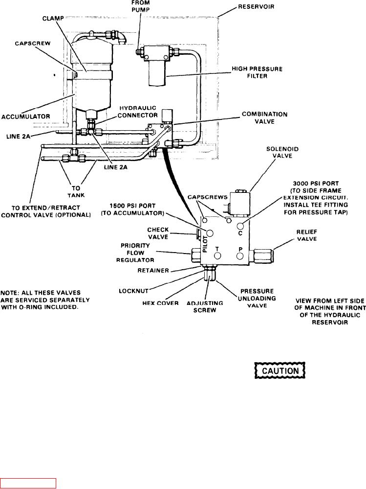
Figure 5D-1. Hydraulic Accumulator and
Combination Valve Installation
To adjust the pressure unloading valve, proceed as follows:
1. Repeat steps 1 and 2 from the previous procedure for
The following steps must be performed care-
checking the relief valve.
fully or damage to the system components can
result. In no case should a pressure adjusting
2. Connect the pressure gauge to the port at line 2A. Plug
screw be turned rapidly, always make adjust-
the line to prevent loss of hydraulic oil.
ments slowly.
3. Start the engine and allow the hydraulic pressure to
A. Loosen the locknut and turn the adjusting screw to ob-
build up to 1400 to 1710 psi.
tain a maximum pressure to 1710 psi.
4. Operate the controls until the pressure drops to 1400
B. Repeat step 4 above.
psi. The unloading valve should close at this point and again
recharge the system.
C. If difficulty is encountered arriving at these settings, re-
place the priority flow regulator and repeat steps A and
5. If the valve does not maintain the pressure as stated in
B.
step 4, remove the hex cover and adjust as follows (see Fig-
D. Tighten the locknut and replace the hex cover.
5D-2

