
SUBSECTION 8D
BOOM HOIST BRAKES
C. Tighten the nut against the top of the spring bracket until
A. Remove pins (22 and 45) to release the tension in cables
assembly pin (71) that was installed during the removal
(31 and 32).
procedure can be removed.
B. Disengage pawls (53 and 56) from the drum ratchets.
D. Pull the assembly pin and back off on the nut to relieve
9. Remove capscrew (62) from bracket (51) and remove rod
the spring pressure. Remove spring bracket (65) and
end (61) from pin (57).
spring (79).
2. Replace springs (09, 17, 76 and 79).
3. If cylinders (13 and 66) leak or have been performing
The next step in this procedure involves re-
erratically, overhaul them. See Subsection 5D.
moving pin (57) from the assembly. When re-
4. Assemble the boom hoist brake cylinder and spring as-
moving pin (57), the drum brake operating
sembly, as follows:
mechanism should be supported so it will not
fall.
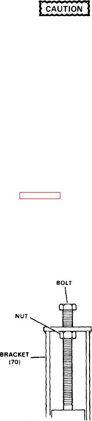
A. Set spring (79) and bracket (65) into bracket (70).
10. Slowly pull pin (57) out of pawl (56), spacer (01), bracket
B. Install a 3/4 x 8 inch bolt into the top of bracket (70) as
(55) and the drum brake operating mechanism.
shown in Figure 8D-4.
11. Remove the drum brake operating mechanism and the
C. Tighten the nut against the bracket until assembly pin
bottom half of the brake band along with it. Then remove the
(71) can be installed through bracket (65) and the drilled
top half of the drum brake band.
hole in bracket (70).
12. Support the planetary brake operating mechanism and
NOTE
pull pin (57) completely out.
The assembly pin is removed after the bracket as-
13. Raise the planetary operating mechanism into the
sembly is installed on the machine.
space above its normal position, remove cotter pin (25) and
D. Remove the nut and bolt from the top of bracket (70) and
pin (23).
install cylinder (66) and spacer (67). Secure with lock-
14. Remove the planetary brake operating mechanism,
washer (69) and capscrew (68).
then the top and lower halves of the brake bands.
5. Remove the lining from the bands, check the bands for
INSPECTION AND REPAIR. Prior to installation of the brake
distortion, then install new lining (06 and 73).
bands on the drum, check and repair the brakecomponents
as follows (see Figure 8D-5):
NOTE
1. Disassemble the boom hoist brake cylinder and spring
A lining kit is available. See the Replacement Parts
assembly as follows:
Manual.
A. Remove capscrews (68) and lockwasher (69) from cyl-
6. Inspect the brake drums to see that they are not cracked,
inder (66). Remove the cylinder and spacer (67) from the
scored or otherwise damaged.
bracket.
7. Inspect the pawls and ratchet teeth for breaks, cracks or
6. Install a 3/4 x 8 inch bolt with nut into the hole at the top
excessive wear. Replace if necessary.
of bracket (70) as illustrated in Figure 8D-4.
ASSEMBLY AND INSTALLATION. To assemble the boom
hoist brakes and related parts, proceed as follows (see Fig-
ure 8D-5):
1. Check the adjustment of pawls (53 and 56). See Sub-
section 8F for this procedure.
2. Attach the planetary brake operating mechanism to
lower band (05) with pin (23). Install with the head end of
the pin towards pawl (53) and fasten with cotter pin (25).
3. Install lower band (05). then upper band (05). Now in-
sert pin (57) through the dead end of the upper band into
pawl (53).
4. Assemble the drum brake operating mechanism to lower
band (73) with pin (64). Install cotter pins (63 and 78).
5. Install lower half of band (72) and operating mechan-
ism. Support the operating mechanism and install the
upper half of the band.
6. Press pin (57) through the dead end of the upper band
and bracket (55).
Figure 8D-4. Assembly Bolt
8D-3

