
PROPEL TRANSMISSION
SUBSECTION 9B
3. Install the motor on the brake plate. Assemble the motor
REPAIR
to the brake plate and install the capscrews. Care should be
GENERAL. If a problem exists in a pump controller it is rec-
taken in tightening the capscrew to prevent misalignment.
ommended that the valve be replaced with a new unit. The
Torque the mounting capscrews to 65 ft-lbs lubricated.
repair information provided here is limited to the replace-
ment of seals, O-rings and orifices. At no time should any
attempt be made to repair or alter the electronic amplifrer
NOTE
unit contained in the controller.
Install the left propel motor with Port B towards the
side frame Install the right propel motor with Port A
DISASSEMBLY To disassemble the propel controller, pro-
towards the side frame.
ceed as follows (see Figure 9B-30):
1. Place the controller with the nameplate up on a clean
CONTROLLER (45Q39)
level surface. Orient the mounting face away from the as-
DESCRIPTION
sembler.
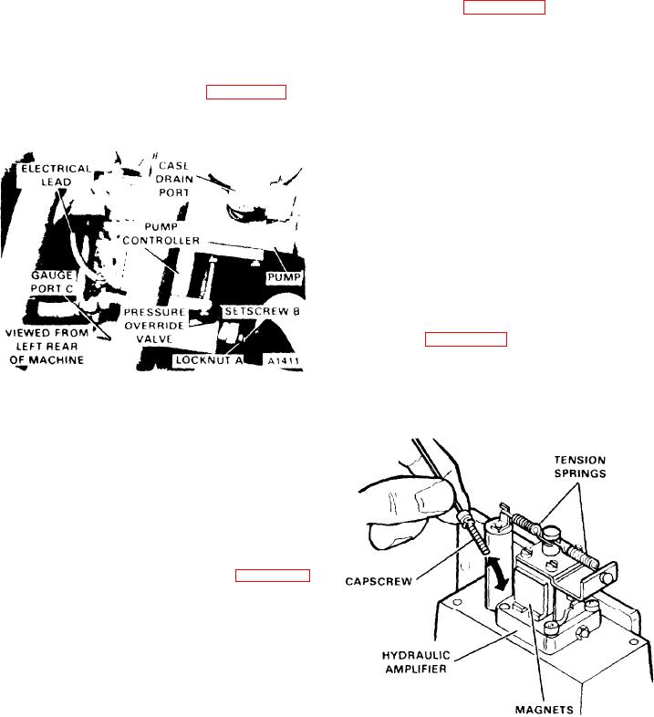
Each pump has a controller mounted between the pres-
2. Use a 5/64 inch Allen wrench to remove screws (22).
sure override valve and the pump (see Figure 9B-27). The
3. Using a 9/64 inch Allen wrench, remove two cap-
controller has internal linkage connected to the pump servo
screws (23) and lockwashers (24).
controls.
4. Slide motor cap (03) toward electrical connector (01)
until the motor cap bottoms.
5. Carefully push the electrical connector into motor cap
(03).
6. Remove the motor cap, gasket (06), and electrrcal con-
nector gasket (02).
7. Mark the coil leadwires for assembly. Slide the teflon
sleeving back, and note which coil leadwires are soldered to
each connector pin to ensure wiring during assembly.
wires from the electrical connector terminals Disconnect
both tension springs from the top of the hydraulic amplifier
assembly (see Figure 9B-28).
9. With a 3/32 inch Allen wrench, remove four socket head
capscrews (25) and lockwashers (26). Do not let the screws
Figure 9B-27. Pump Controller and
or washers rub the magnets (see Figure 98-28).
Pressure Override Valve
The controller is an electrohydraulic servo valve which-re-
ceives signals from the propel control module in the oper-
ator's cab. The controller converts the electrical signals to a
mechanical movement of the control valve spool. The valve
spool directs hydraulic fluid to the pump servos which
change the angle of the pump swash plate and thus the
output of the pump.
REMOVAL
To remove the controller, proceed as follows (see Figure 9B-
27):
1. Stop the engine and disconnect the battery cable.
2. Remove the electrical lead from the controller.
3. Remove the capscrews securing the pressure override
valve to the controller and Iift the override valve away from
the controller.
4. Remove the capscrews securing the controller to the
pump.
5. Carefully pull the controller away frorn the pump case
and disconnect and control linkage.
Figure 9B-28. Tension Spring and Capscrew Removal

