
SUBSECTION 9B
PROPEL TRANSMISSION
head capscrews (23) and lockwashers (24). Torque the
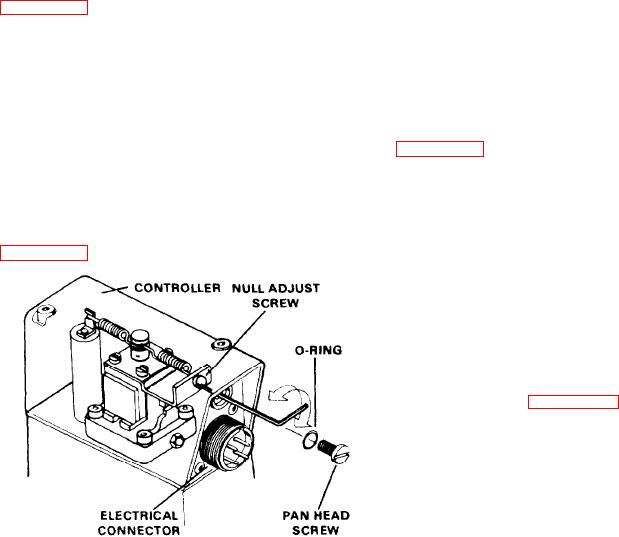
1. Ensure that zero electrical signal is applied to the con-
screws to 30 inch-lbs. Replace the nameplate if it was re-
troller by disconnecting the electrical lead to the controller.
moved.
2. Using a blade screwdriver, remove the pan head screw
24. Install pan head screw (04) and O-ring (05).
and O-ring to permit access to the null adjust screw.
25. Install the controller on the propel pump but do not con-
3. With the pump running, use a 2-1/2 inch long, 1/8 inch
nect the electrical lead.
Allen wrench to slowly rotate the null adjust screw in each
direction (clockwise and counterclockwise), in turn. Note
26. Start the engine and visually examine for evidence of
the relative position of the null adjust screw at the moment
external leakage. If leakage is present and cannot be cor-
the machine begins to propel, for each direction of null ad-
rected by replacing O-rings and/or seal plates, replace the
just screw rotation.
leaking components.
4. Position the null adjust screw at a position approxi-
27. Adjust the mechanical null of the controller as de-
mately centered within the "deadband" between the two
scribed in the following topic, Null Adjustment.
positions noted in step 3. Normal adjustment should re-
28. Rotate the manual override lever and observe pump
quire less than one-quarter turn.
output flow. Motor output should be the same in both di-
5. After the desired flow null has been obtained, reinstall
rections.
the pan head screw and O-ring.
29. If a noticeable variance in pump output exists, remove
6. Connect the electrical lead to the connector.
the motor cap assembly and carefully align the mating sur-
faces of the motor cap assembly and controller body.
PRESSURE OVERRIDE VALVE
30. Repeat steps 27 and 28 as required to achieve near
DESCRIPTION. The pressure override valve is mounted on
equilibrium of pump flow.
the electric controller on the side of the pump. The override
will automatically destroke the pump once the desired
INSTALLATION
maximum system pressure (load) is reached. It will main-
tain that system pressure so the load can be held. This pre-
To install a controller on the pump, proceed as follows (see
vents operation of the system relief valves for prolonged
periods and helps reduce heat build-up in the transmis-
1. Place a new gasket on the pump case.
sion.
2. Connect the linkage from the pump to the controller.
The valve pressure is set at the factory, however, this
3. Install the controller capscrews and finger tighten.
setting can be checked and adjusted when a new valve is in-
stalled or if the pressure setting is requied for trouble-
4. Install the pressure override valve and gasket and
shooting purposes.
tighten all capscrews securely.
REMOVAL. To remove the valve, proceed as follows (see
5. Connect the electrical lead to the controller.
ADJUSTMENT
1. Stop the engine and disconnect the battery cable.
Adjustment consists of adjusting the flow null of the con-
2. Remove the two hydraulic lines from the valve.
troller. This is normally done when a new valve is installed
3. Remove the capscrews securing the valve to the electric
or if the machine propels when the operator's controller is
controller and lift the valve away from the controller.
in neutral. To adjust the controller, proceed as follows (see
INSTALLATION. To install a new override valve on the
pump, proceed as follows (see Figure 98-33):
1. Place a new gasket on the controller.
2. Install the override valve to the controller and secure
with capscrews.
3. Connect the two hydraulic lines to the valve.
ADJUSTMENT. To adjust the pressure override valve, pro-
ceed as follows (see Figure 9B-33):
1. Check the controller null adjustment as described pre-
viously in this subsection.
2. Disconnect the electrical wire at the controller to assure
that the controller is in neutral.
3. Inspect the main relief valves to determine the factory
setting. These valves are located in the manifold on the end
of the propel motors and are stamped with a two digit num-
ber that is the main relief setting multiplied by 100 (55 is a
Figure 9B-32. Controller Null Adjustment
5500 psi relief setting).

