
PROPEL GEAR CASE
SUBSECTION 9D
Figure 9D-6. Housing Dimension Location
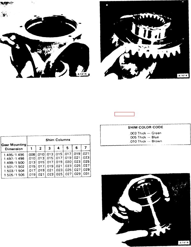
Figure 9D-7 Gear Mounting Dimension
15. When all end play is taken out of the bearings, mea-
NOTE
sure the space beween the cover and input housing in three
For housing dimensions less than 3.807, use
places with a feeler gauge.
3.807/3.808 and subtract a shim thickness equal to
16. Take the average of the three readings and install
the difference between the actual housing dimen-
shims (72) to equal this average Shim color codes are
sion and 3.807. For housing dimensions greater than
shown in Table 9D-3.
3.814, use 3.813/3.814 and add a shim thickness
Table 9D-3. Shim Color Codes
equal to the difference between actual housing di-
mensions and 3.814.
Table 9D-2. Shim Distance
17. Coat O-ring (71) with grease and install on the cover.
18. Install all capscrews (75) and lockwashers (74) and
tighten to 80-90 ft-lbs.
19. Determine the gear mounting dimension from gear (37)
and record for future use (see Figure 9D-8).
7. Construct a shim set to obtain the shim distance deter-
mined in step 6.
8. Install shim set (64) into the bore of input housing (57).
9. Press bearing cup (65) into the bore of the input housing
with the thin edge out.
10. Press cone (66) onto the end of shaft (67) and install
this assembly into the input housing.
11. Slide gear (68) onto shaft (67) and then press cone (69)
onto the shaft with the thin edge out.
12. Press cup (70) into cover (73).
13. Place the cover on the input housing and install two
capscrews (75) 180 apart.
14. Tighten the capscrews down evenly and gradually
Figure 9D-8 Gear Mounting Dimension
while turning shaft (67).
9D-4

