
Installation
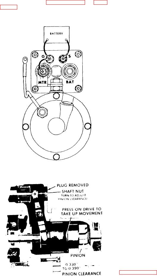
3. Measure the distance between drive
and housing (see Figure 10D-9 on page
proceed as
starter,
the
install
To
follows:
4. Adjust clearance by removing plug
1. Set the motor into the flywheel hous-
and turning shaft nut.
ing.
2. Support the motor and install the
b o l t s and lockwashers used to secure the
motor to the flywheel housing. Tighten
the attaching bolts to 137-147 ft-lbs tor-
que.
3. Make sure electrical connections are
Install wires as marked earlier
clean.
and tighten hardware.
Description
is a
system
charging
integral
The
self-rectifying, brushless unit wit a built
in regulator. The only moveable part is
the rotor which is mounted on a ball
bearing on the drive end, and a roller
bearing at the rectifier end. All current
stationary.
are
conductors
carrying
These conductors are the field winding,
the stator windings, the six rectifying
diodes, a n d t h e r e g u l a t o r c i r c u i t c o m -
The regulator and diodes are
ponents.
e n c l o s e d in a sealed compartment.
F i g u r e 10D-8. Checking Pinion
Clearance Circuit
A fan located on the drive end provides
Extra large grease
airflow for cooling.
reservoirs contain an adequate supply of
lubricant so that no periodic maintenance
is required. Only one wire is needed to
connect the charging system (alternator)
to the battery, along with an adequate
The output terminal is
ground return.
connected directly to the battery positive
terminal.
The hex head bolt on the output terminal
is electrically insulated; no voltage read-
ing can be obtained by connecting to the
h e x head bolt.
Operation
The basic operating principles are ex-
in
shown
and
below
plained
Figure 10D-10 on page 10D-9.
As the rotor begins to turn, the perma-
F i g u r e 10D-9. Measuring Pinion
nent magnetism therein induces voltages
Clearance

