
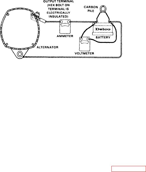
Figure 10D-12. Output Check
2. If voltage exceeds 30 volts, remove
NOTE
the alternator for repair.
Initial voltage build-up is by resi-
3. If voltage does not exceed these val-
dual magnetism in the rotor. In-
ues, proceed as follows:
crease the speed as required to
obtain maximum current output.
A . Insure that accessories have not been
left on for extended periods.
6. If ampere output is not within 10 am-
B. C h e c k t h e d r i v e b e l t f o r p r o p e r t e n -
peres of rated output as stamped on the
sion.
alternator frame, remove the alternator
f o r r e p a i r . If ampere output is within 10
C. Inspect
t h e wiring
for defects
amperes of rated output as stamped on
Check all connections for tightness
the alternator frame, the alternator is
and cleanliness, including the cable
not defective.
In this case, an adjust-
clamps and battery posts.
ment of the voltage setting may correct
the condition.
Connect a voltmeter from output terminal
on the alternator to ground.
7. Adjust the voltage setting as follows:
A zero
reading indicates an open between volt-
meter connection and battery.
A. Remove cover to expose potentiometer
a s s h o w n i n Figure 10D-13 on page
If previous steps check satisfactorily,
10D-12.
check the alternator as follows:
B. Turn potentiometer one or two notch-
1. Disconnect the battery ground cable.
es clockwise to raise the voltage set-
one
or
ting
and
notches
two
counterclockwise to lower the voltage
2. Connect an ammeter in the circuit at
setting.
the output terminal of the alternator.
C. Install cover.
3. Reconnect the battery ground cable.
After adjusting setting, check for an im-
4. Turn on accessories. Connect carbon
proved battery condition over a service
pile across the battery.
period of reasonable length. If adjusting
the setting does not correct the battery
5. Operate the engine at moderate speed
condition, remove the alternator for re-
as required, usually 4000 alternator RPM
pair.
o r m o r e , and adjust the carbon pile as
to obtain maximum current
required,
Remember that if the battery state of
output.
charge is low, the regulator may not be
limiting the voltage, and turning the ad-
Electrical Components
10D-11

