
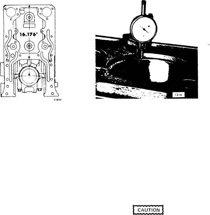
F i g u r e 11B-18. Checking Cylinder
Figure 11B-17. Centerline of
L i n e r Counterbore with J 22273
Crankshaft to Top of Block
7. Check the main bearing bores as fol-
C. If stock is removed from the top sur-
lows:
face of the block, check the depth of
the seal ring grooves and counter-
A. Check the bore diameters with the
The cylinder head seal strip
bores.
main bearing caps in their original
grooves must be 0.092"-0.107" deep.
positions. Apply a small quantity of
The large water hole counterbores
International Compound No. 2, or
(between the cylinders) must be
equivalent, to the threads on the
0.109"-0.120" deep and the combina-
bolts or studs and nuts and to the
tion water and oil hole counterbores
bolt head (or nut) contact area.
and
small
water
holes
must
be
Then install and tighten the bolts to
0.087"-0.098"
deep.
If
necessary,
165-175 lb-ft (224-238 Nm) torque or
deepen the grooves or counterbores
stud nuts to 140-155 lb-ft (190-211
to the specified limits to retain the
Nm) torque. The specified bore di-
proper "crush" on the seal rings. It
ameter is 3.812" to 3.813". If the
is not necessary to deepen the coun-
bores do not fall within these limits,
terbores of the cylinder liners since
the cylinder block must be rejected.
0.004" and 0.008" undersize thickness
inserts are available for adjusting the
liner position.
6. Make sure the cylinder liner counter-
Main bearing cap bolts are espe-
bores in the block are clean and free of
cially designed for this purpose
dirt.
Then
check
the
depth
and must not be replace by ordi-
(Figure 11B-18). The depth must be
n a r y bolts.
0.4770" to 0.4795" and must not vary
more than 0.0015" throughout the entire
circumference. The counterbore sur-
NOTE
faces must be smooth and square with
the cylinder bore within 0.001" total in-
Bearing caps are numbered to cor-
dicator reading. There must not be over
respond with their respective posi-
0.001" difference between any two adja-
tions in the cylinder block. It is
cent cylinder counterbores when
imperative that the bearing caps
measured along the cylinder longitudinal
are reinstalled in their original po-
centerline of the cylinder block.
sitions to maintain the main bear-
ing bore alignment. The number
of the front main bearing cap is
stamped on the face of the oil pan
mounting flange of the cylinder

