
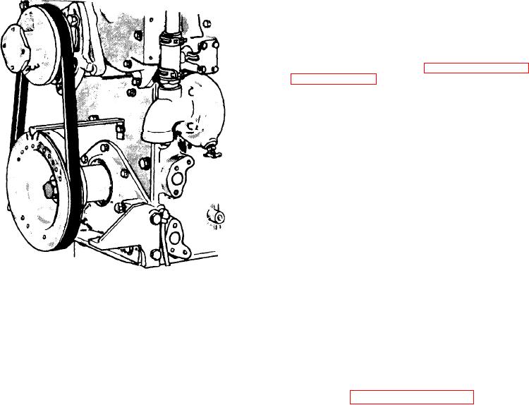
17. Turn the crankshaft, in the direction
o f e n g i n e rotation, u n t i l t h e e x h a u s t
valves in the cylinder selected are com-
pletely open.
Re-install the dial indica-
tor so the indicator spindle rests on top
of the injector follower (Figure 11B-146
on page 11B-96). Then set the indicator
on zero. Next turn the crankshaft slow-
ly in the direction of engine rotation
until the center mark on the pulley is in
line with the pointer.
18. Note the indicator reading. The cor-
rect timing should be 0.230"; retarded
timing should be 0.197" and advanced
timing should be 0.262".
19. After completing the timing check,
remove the dial indicator.
Also remove
the pointer from the crankshaft front
cover.
20. Install the valve rocker cover.
Figure 11B-145. Pointer Installation
for Marking Top-Dead Center
CAMSHAFT, BALANCE SHAFT AND
11. Scribe a line on the vibration damper
in line with the end of the pointer.
Description
12. Slowly turn the crankshaft opposite
the direction of engine rotation until the
indicator hand stops moving.
Continue
The camshaft and the balance shaft are
turning the crankshaft until the indica-
located just below the top of the cylinder
tor hand starts to move again.
block (see Figure 11B-147 on page
11B-96) and each may be located on ei-
13. Set the dial indicator to zero. Turn
ther side of the engine as required by
the crankshaft until the indicator read-
engine rotation and accessory arrange-
ing is 0.010".
ment.
The
camshaft
actuates
the
exhaust valve and injector operating me-
14. Scribe a second line on the vibration
chanism.
damper in line with the end of the point-
er.
The accurately ground cams ensure effi-
cient, quiet cam follower roller action.
15. Scribe a third line halfway between
The are also heat treated to provide a
first
the
This
lines.
is
hard wear surface.
two
top-dead-center.
The
three
scribed
lines are shown on the crankshaft pulley
Both ends of the cam and balance shaft
in Figure 11B-145. Remove the indicator
are s u p p o r t e d b y b e a r i n g a s s e m b l i e s ,
and rod from the engine.
each consisting of a flanged housing and
two bushings.
In addition, intermediate
two piece bearings support the camshaft
NOTE
uniform
intervals
at
throughout
its
If the crankshaft pulley retaining
length.
The intermediate bearings are
secured to the camshaft by lock rings,
bolt has loosened, tighten it to the
thereby permitting them to be inserted
specified torque.
into the cylinder block with the shaft.
Each intermediate bearing is secured in
16. Install the injector as outlined in
place, a f t e r t h e c a m s h a f t i s i n s t a l l e d ,
Subsection 11C.
Then refer to 11H and
with a lock screw threaded into a coun-
adjust the valve clearance and time the
terbore in the top of the cylinder block.
injector.
E n g i n e (Less Major Assemblies)

