
8. Remove the lock screws that secure
the camshaft intermediate bearings.
9. Remove the three bolts that secure
the camshaft bearing to the front end
plate.
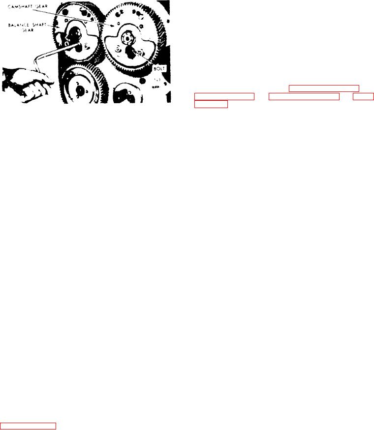
10. Install the camshaft gear puller J
1902-01, four spacers J 6202-2 and cam-
shaft gear puller adaptor plate J 6202-1
on the camshaft gear (Figure 11B-152 on
page 11B-99 and Figure 11B-153 on page
Figure 11B-151. Removing or
11. Turn the center screw of the puller
Installing Shaft Bearing Retainer
clockwise to disengage the camshaft from
Bolts
the camshaft gear.
12. Withdraw the camshaft bearing and
NOTE
gear assembly and the balance shaft and
gear from the rear end of the cylinder
Do not remove the puller or the
block.
adaptor plate until the camshaft is
The adaptor plate,
reinstalled.
13. The cam and balance shaft front end
secured to both the flywheel hous-
bearings may be removed after taking
i n g a n d t h e c a m s h a f t g e a r , will
out the bolts that hold the bearings to
hold the gear (also the thrust
the end plate and cylinder block. If ne-
washer) securely in place and in
cessary, use a pry bar under the bear-
alignment which will aid in the re-
ing flange.
i n s t a l l a t i o n of the camshaft.
R e m o v e Camshaft (Flywheel Housing and
12. Remove the front bearing from the
T o r q u e Converter in Place)
camshaft.
Then pull the camshaft and
intermediate bearing from the cylinder
The camshaft may be removed and re-
block.
placed w i t h o u t r e m o v i n g t h e f l y w h e e l
housing and disconnecting the torque
converter if there is space enough to
slide the shaft out through the front of
D i s a s s e m b l e Camshaft and Balance Shaft
the engine.
1. Remove the gear from the shaft.
1. Drain the engine cooling system.
2. Slide the rear bearing (and the thrust
2. Remove all of the accessories and as-
washer) off of the shaft.
semblies that are necessary to facilitate
the removal of the flywheel housing hole
3. Remove the lock rings from the cam-
cover over the front balance weight cov-
shaft intermediate bearings and free the
er.
two halves of each bearing.
3. Remove the cylinder head.
4. To facilitate the removal of any for-
eign material lodged behind the plugs,
4. Remove the front balance weight cover
remove the end plugs from each camshaft
and place a wood block between the bal-
as follows:
(see Figure 11B-150 on
ance w e i g h t s
A . Clamp the camshaft in a vise equipped
with soft jaws, being careful not to
5. Remove the gear nut retainer after
damage the cam lobes or machined
removing the bolts.
surfaces of the shaft.
6. Loosen and remove the nut at each
B. Make an indentation in the cylinder of
end of the camshaft.
the camshaft end plug with a 31/64"
drill (carboloy tip).
7. Remove the front balance weights.

