
Idler Gear Parts
in accordance with design requirements
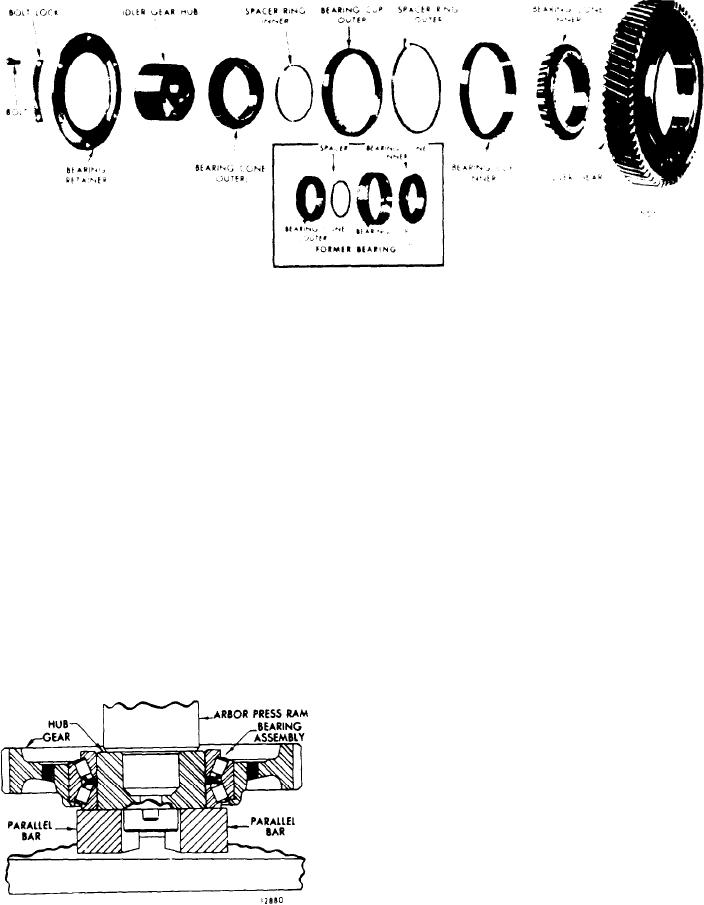
6. Position the gear with both cups over
to provide a rigid idler gear and bearing
the hub and the inner bearing cone.
As the bearing cones are
assembly.
moved toward each other in a tapered
7. Press the outer idler gear bearing
roller bearing assembly, the rollers will
cone over the hub while rotating the
be more tightly held between the cones
gear to seat the roller properly between
In the idler gear bearings, a
and cup.
The bearing cones must be
the cones.
slight pre-load is applied by means of a
supported so as not to load the bearing
selected spacer ring between the bearing
rollers during this operation (see
cones, t o p r o v i d e r i g i d i t y o f t h e g e a r
Figure (11B-164).
and bearing assembly when it is mounted
o n i t s h u b . This method of pre-loading
8. Before installing the gear and bearing
i s measured, i n t e r m s o f p o u n d - p u l l , b y
assembly, check the pre-load.
the effort required at the outer diameter
of the gear to turn the bearing cup in
r e l a t i o n to the bearing cones.
C h e c k Pre-Load of Bearing
A n y time an idler gear assembly has been
The rollers of the bearing are loaded be-
removed from an engine for servicing or
tween the bearing cup and bearing cones
inspection, while performing engine ov-
erhaul or other repairs, the pre-load
should be measured as part of the opera-
tion.
The idler gear bearing must be clean and
lubricated with light engine oil prior to
Idler gear assemblies
the pre-load test.
which include new bearings should be
worked in by grasping the gear firmly
by hand and rotating the gear back and
forth several times.
After the idler gear, hub and bearing
are assembled together, t h e b e a r i n g
should be checked to ascertain that the
gear may be rotated on its bearing with-
out exceeding the maximum torque spec-
ifications, nor be so loose as to permit
F i g u r e 11B-164. P r e s s i n g H u b i n t o
the gear to be moved in relation to the
Bearing

