
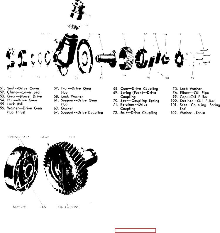
Figure 11B-173. Blower Drive Gear Parts
6. Insert the blower drive shaft into the
blower rotor gear hub. The end without
the groove for the ring must be inserted
first.
7. Lock the drive shaft in place by in-
stalling the ring in the groove provided
in the coupling cam.
8. Re-install the flywheel and flywheel
housing and install the remaining bolts
that secure the blower drive gear and
support assembly.
BALANCE WEIGHT COVER
Figure 11B-175. Relation of Blower
Description
D r i v e Cam to Oil Grooves in Gear Hub
The
balance
weight
cover
front
2. Place a new gasket (63) on the mount-
(Figure 11B-176 o n p a g e 1 1 B - 1 1 6 ) e n -
ing face of the hub support.
closes the front engine balance weights
and also serves as a support for various
3. Attach the blower drive gear and
equipment such as the cooling fan sup-
support assembly to the cylinder block
port bracket.
rear end plate with the two 3/8"-24 x 7/8
bolts.
The balance weight cover requires no
servicing.
However, when an engine is
4. Connect the oil line.
being completely reconditioned or the
camshaft, balance shaft or front balance
5. Install the blower as outlined in Sub-
weights
need
replacing,
the balance
section 11D and secure seal (61) and
weight cover must be removed.
clamp (52) as shown in Figure 11B-173.
Engine (Less Major Assemblies)

