
Figure 11C-12. Injector Test
C l a m p i n g Heads
diameter hole at the far right of the
a d a p t o r p l a t e o n t o t h e 3 / 8 " diameter
dowel pin. This allows the adaptor plate
to swing out for mounting the fuel injec-
tor.
5. Mount the injector through the large
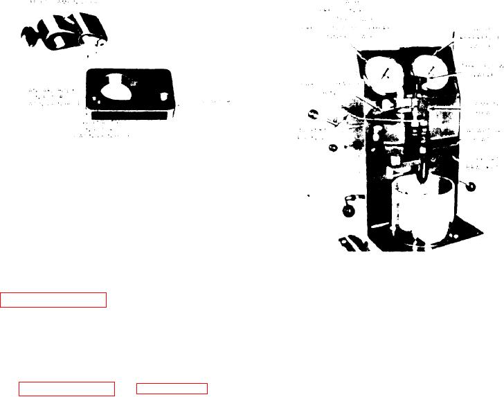
Figure 11C-13. Injector Installed in
hole and insert the injector pin in the
Tester J 23010
(see
hole
pin
locating
proper
NOTE
6. Swing the mounted injector and adapt-
The Thru-Flow valve should still
or plate inward until they contact the
turn freely. If it does not, turn
stop
pin
at
the
rear
of
the
support
the valve counterclockwise until it
bracket.
rotates freely and reapply clamp-
ing pressure.
CLAMPING THE FUEL INJECTOR. Refer
to Figure 11C-14 on page 11C-9 and po-
Excessive force on lever 1 during
the injector tester levers as
sition
clamping can damage the seals in
follows:
the
valves
operated
by
4
and 5.
Lever
2
up and to the rear
Lever
3
in the rear detent
Lever
4
up (horizontal)
PURGING AIR FROM THE SYSTEM.
Lever
5
up (horizontal)
Move lever 4 down and operate pump le-
ver 1 to produce a test oil flow through
1. Align the clamp head nylon seals over
t h e i n j e c t o r . When air bubbles no longer
(see
caps
filter
injector
the
pass through the clear discharge tubing,
Figure 11C-13).
the system is free of air and is now
ready for testing.
2. Back off the Thru-Flow valve about
half-way to allow the self aligning nylon
INJECTOR VALVE OPENING AND
seals to seat properly during the clamp-
SPRAY PATTERN TEST. This test de-
ing operation.
termines spray pattern uniformity and
the relative pressure at which the injec-
3. Hold the clamping head in position
injection
and
fuel
opens
valve
tor
over the filter caps and, with the left
begins.
hand, o p e r a t e p u m p l e v e r 1 e v e n l y t o
move the clamping head down to seal the
1. Clamp the injector properly and purge
filter caps.
t h e air from the system.
2 . Move lever 4 down.

