
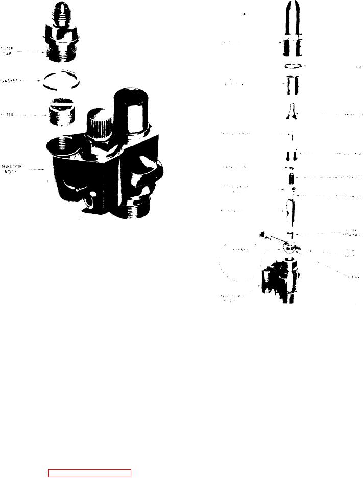
11C-35. Details of Injector
Filters and Caps
4. Place the check valve (without the
0.010" hole) centrally on top of the bush-
ing. Then place the check valve cage
over the check valve and against the
bushing.
5. Insert the spring seat in the valve
spring, then insert the assembly into the
Figure 11C-36. Detailed Parts of
spring cage, spring seat first.
Injector
6. Place the spring cage, spring seat
9. Use socket J 4983-01 and a torque
and valve spring assembly (valve spring
wrench to tighten the injector nut to
down) on top of the check valve cage.
75-85
lb-ft
(102-115
Nm)
as
s h o w n in Figure 11C-39 on page 11C-23.
7. Insert the needle valve, tapered end
down,
inside
of
the
spray
tip
(see
10. After assembling a fuel injector, al-
Figure 11C-3 on page 11C-2). Then
ways check the area between the nut and
place the spray tip and needle valve on
the body. If the seal is still visible after
top of the spring cage with the quill end
the nut is assembled, try another nut
of the needle valve in the hole in the
which may allow assembly on the body
spring cage.
without extruding the seal and forcing it
out of the body-nut crevice.
8. Lubricate the threads in the injector
nut and carefully thread the nut on the
NOTE
injector body by hand. Rotate the spray
Do
not
exceed
the
specified
tip between your thumb and first finger
torque. Otherwise, the nut may
while threading the nut on the injector
be stretched and result in improp-
body
(see
on
page
er sealing of the lapped surfaces
11C-22). Tighten the nut as tight as
in a subsequent injector overhaul.
possible by hand. At this point there
should be sufficient force on the spray
tip to make it impossible to turn with
your fingers.
Fuel System and Governor

