
plate and secure it in place with "V"
band coupling (1). Lightly lubricate the
threads of the toggle bolt with engine oil
and tighten the nut to 110-130 lb-in
(12-15 Nm) torque.
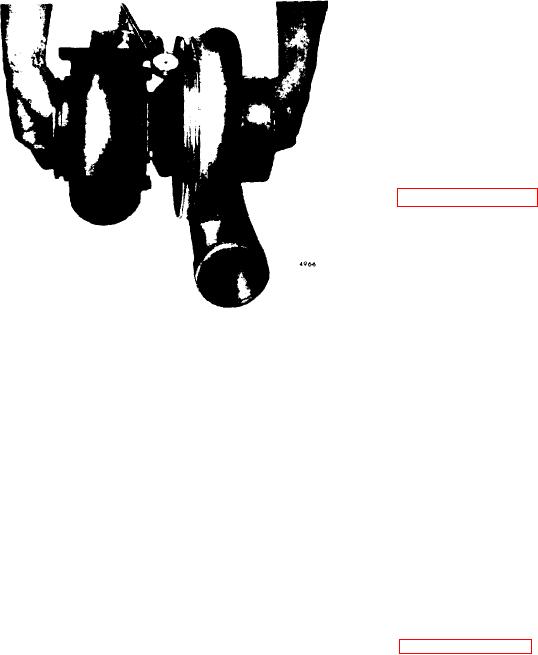
21. Check the shaft radial movement:
A. Position the magnetic base J 7872-2
with the swivel adaptor J 7872-3 on
the flat surface of the turbine hous-
inlet
shown
in
flange as
ing
B. Fasten the dial indicator extension
rod J 7872-1 to the dial indicator J
8001-3 and attach the dial indicator to
the swivel adaptor.
C. Insert the extension rod J 7872-1 into
the oil drain tube mounting pad open-
Figure 11D-33. Checking Shaft Radial
ing so that the rod is against the
Movement
wheel shaft and is perpendicular to
the shaft.
C. Move the shaft axially back and forth
Total indicator reading
by hand.
NOTE
should be between
(thrust float)
If the total dial
0.003" and 0.010".
Make sure the extension rod does
indicator readings do not fall within
not make contact with the sides of
the specified limits, repair or replace
the center housing.
Otherwise it
the rotating assembly.
will be impossible to obtain an ac-
curate reading.
turbine housing
18. Position
(6)
as
marked at disassembly against the center
housing and secure it in place.
D. Grasp each end of the rotating as-
sembly and, applying equal pressure
19. Secure the turbine housing with "V"
at each end, move the rotating shaft
band coupling (28). Tighten the toggle
first forward and then away from the
n u t as follows:
dial indicator, creating a transverse
movement
the
shaft
in
(see
A. Lubricate the toggle bolt threads with
The dial indicator
a high temperature anti-seize com-
displacement should be between
pound such as Jet Lube (Mil Spec
0.003" and 0.007".
If the displace-
A-907D), or equivalent.
ment does not fall within these limits,
disassemble and repair or replace the
B. Tighten the nut on the "V" band tog-
rotating assembly.
gle bolt to approximately 160 lb-in (18
Nm) torque.
22. If it is to be stored, lubricate the
unit internally and install protective cov-
NOTE
e r s on all openings.
Do not pull a misaligned turbine
23. Stamp the letter "R" in the lower left
housing into alignment with the
hand corner of the name plate to identify
"V" band coupling. The parts
that the turbocharger has been
must be aligned and seated first.
reworked.
C. Loosen the "V" band coupling nut to
Install
Turbocharger
approximately 50 lb-in (6 Nm) torque,
then retorque the nut to 152-168 lb-in
If a turbocharger is to be installed on a
(17-19 Nm) torque.
new or overhauled engine, operate the
engine for approximately one hour before
20. Position compressor housing (2) as
the turbocharger is installed. This must
marked at disassembly against the back-

