
2. Loosen the lock nut (Figure 11H-5)
and back out the buffer screw approxi-
mately 5/8".
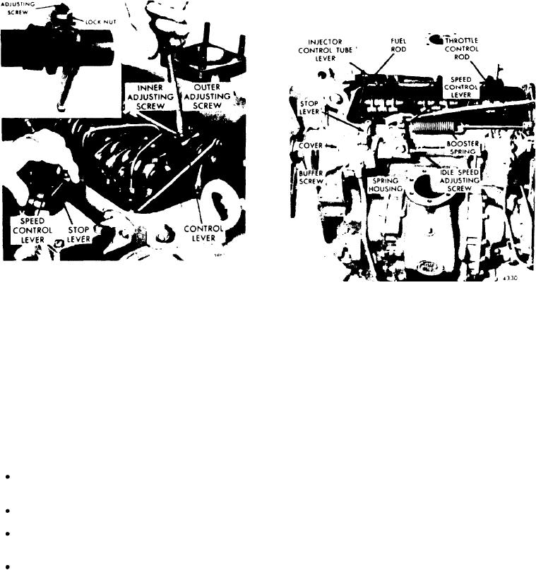
Figure 11H-4. Positioning No. 1
Injector Rack Control Lever
Figure 11H-5. Buffer and Idle Speed
Adjusting Screw
P o s i t i o n Injector Rack Control Levers
3. Loosen all the inner and outer adjust-
The position of the injector control rack
ing screws (Figure 11H-4). Be sure all
levers must be correctly set in relation
the injector rack control levers are free
to the governor.
on the injector control tubes.
Their position determines the amount of
4. Move the speed control lever to the
fuel injected into each cylinder and en-
m a x i m u m speed position.
sures equal distribution of the load.
5. Move the stop lever to the run posi-
Properly positioned injector rack control
tion.
Hold it in that position with light
levers with the engine at full load will
finger pressure. Turn the inner adjust-
result in the following:
ing screw of the No. 1 injector rack con-
trol lever down until a step up in effort
Speed
control
lever
at
the
maximum
is noted. This will place the No. 1 injec-
speed position.
tor rack in the full fuel position. Turn
down the outer adjusting screw until it
Stop lever in the RUN position.
bottoms lightly on the injector control
tube. Then alternately tighten both the
inner and outer adjusting screws.
High speed spring plunger on the seat
in the governor control housing.
NOTE
Injector fuel control racks in the full
fuel position.
Overtightening of the injector rack
control lever adjusting screws dur-
Adjust the No. 1 injector rack control le-
ing installation or adjustment can
result in damage to the injector
ver (Figure 11H-4) first, to establish a
control tube. The recommended
guide for adjusting the remaining injec-
torque of the adjusting screws is
tor rack control levers.
24-36 lb-in (3-4 Nm.)
1. Disconnect any linkage attached to the
The above step should result in
stop lever.
placing the governor linkage and
control tube assembly in the same
Engine Tune-Up

