
position that they will attain while
The setting is too tight if when moving
the engine is running at full load.
the stop lever from the stop to the RUN
position, the injector rack becomes tight
before the stop lever reaches the end of
its travel as determined by the stop un-
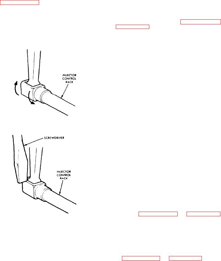
6. To be sure the control lever is prop-
der the governor cover. This will result
erly adjusted, hold the speed control le-
in a step up in effort required to move
ver in the maximum speed position and
the stop lever to the end of its travel.
press down on the injector rack with a
To correct this condition, back off the
screw driver or finger top and note "ro-
inner adjusting screw slightly and tight-
tating" movement of the injector control
en the outer adjusting screw slightly.
rack (Figure 11H-6) when the speed con-
trol lever is in the maximum speed
7. Manually hold the No. 1 injector rack
position
and,
using
a
screw
driver,
in the full fuel position and turn down
press downward on the injector control
the inner adjusting screw (Figure 11H-4
rack. The rack should tilt downward
on page 11H-5) of the No. 2 injector un-
(Figure 11 H-7) and when the pressure of
til the injector rack has moved into full
the screw driver is released, the control
fuel position and the inner adjusting
rack should "spring" back upward.
screw is bottomed on the injector control
tube. Turn the outer adjusting screw
down until it bottoms lightly on the injec-
tor
control
tube.
Then
alternately
tighten both the inner and outer adjust-
ing screws until tight.
8. Recheck the No. 1 injector rack to be
sure that it has remained snug on the
ball and of the rack control lever while
positioning the No. 2 injector rack. If
the rack of the No. 1 injector has become
loose, back off slightly the inner adjust-
ing screw on No. 2 injector control
lever. Tighten the outer adjusting
4238
screw.
9. Position the remaining injector rack
Figure 11H-6. Checking Rotating
control levers as outlined in Steps 7 and
Movement Of Injector Control Rack
8.
A d j u s t Maximum No-Load Speed
The maximum no-load speed on engines
equipped with variable speed governors
must not be less than 125 rpm or more
than 150 rpm above the recommended full
l o a d speed.
With a hand tachometer determine the
maximum n o - l o a d s p e e d o f t h e e n g i n e
then, make the following adjustments, if
required:
11610
1. Refer to Figure 11H-5 on page 11H-5
and disconnect the booster spring.
Figure 11H-7. Checking Injector
Control Rack "Spring"
2. Remove the two bolts and withdraw
the variable speed spring housing and
If the rack does not return to its original
the variable speed spring plunger from
position, it is too loose. To correct,
inside the spring housing.
back off the outer adjusting screw slight-
ly and tighten the inner adjusting screw
A split stop can only be used with a solid
slightly.

