
A thermostat is used in the engine to
3. Move the spring retaining bolt in the
control the coolant flow. Therefore, be
slot of the speed control lever until the
sure it is in place and fully operative or
center of the bolt is on or slightly over
the engine will overheat during the
center (toward the idle speed position)
Run-In. However, if the dynamometer
of an imaginary line through the bolt,
has a water standpipe with a temperature
lever shaft and eye bolt. Hold the bolt
control regulator, such as a Taylor valve
and tighten the lock nut.
or equivalent, the engine should be test-
ed without the thermostat.
4. Start the engine and move the speed
control lever to the maximum speed posi-
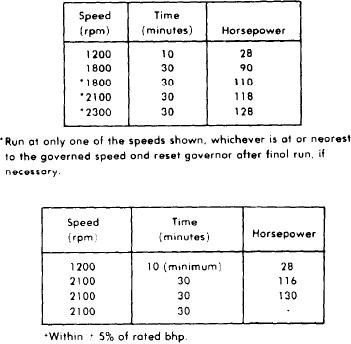
The Basic Engine Run-In Schedule is
tion and release it. The lever should re-
shown in the following table. The hor-
turn to the idle speed position. If it
sepower shown is at SAE conditions; dry
does not, reduce the booster spring ten-
air density 0.0705 Ib/cu. ft (1.129
sion. If it does, continue to increase the
kg/m 3), air temperature of 85F
spring tension until the point is reached
(29.4C), and 500 ft. (152 m) elevation.
where it will not return to idle. Then
reduce the spring tension until the lever
does return to idle and tighten the lock
nuts on the eye bolt. This setting will
BASIC ENGINE RUN-IN SCHEDULE
result in the minimum force required to
operate the speed control lever.
ENGINE RUN-IN INSTRUCTIONS
General
Following a complete overhaul or any ma-
jor repair job involving the installation of
piston rings, pistons, cylinder liners or
bearings, the engine should be "Run-In"
FINAL ENGINE RUN-IN SCHEDULE
on a dynamometer prior to release for
service.
The dynamometer is a device for apply-
ing specific loads to an engine. It per-
mits the serviceman to physically and
visually inspect and check the engine
while it is operating. It is an excellent
method of detecting improper tune-up
misfiring injectors, low compression and
other malfunctions, and may save an en-
D y n a m o m e t e r Test and Run-In Proce-
g i n e from damage at a later date.
dures
The operating temperature within the
THE BASIC ENGINE. The great number
engine affects the operating clearances
of engine applications make any attempt
between the various moving parts of the
to establish comparisons for each indi-
engine and determines to a degree how
vidual model impractical. For this
the parts will wear. Normal coolant tem-
reason, each model has basis engine rat-
perature (160-185F or 71-85C) should
ing for comparison purposes.
be maintained throughout the Run-In.
A basic engine includes only those items
The rate of water circulation through the
actually required to run the engine.
engine on a dynamometer should be suf-
The addition of any engine driven acces-
ficient to avoid having the engine outlet
sories will result in a brake horsepower
water temperature more than 10 higher
figure less than the values shown in Bas-
than the water inlet temperature.
ic
Engine
Run-In
Schedule.
The
Though a 10 rise across an engine is
following items are included on the basic
recommended, it has been found that a
engine: blower, fuel pump, water pump,
15 temperature rise maximum can be
and
governor.
The
fan
and
permitted.
battery-charging generator typify acces-
11H-8

