TM 10-3950-206-12
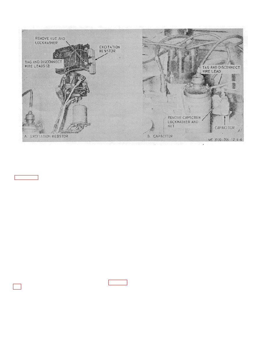
Figure 4-6. Radio interference suppression components.
Section VIII. ELECTRICAL SYSTEM MAINTENANCE
rectification. It is used to:
4-20. General
(1) Automatically connect the voltage regulator
The electrical wiring diagram for the crane is shown in
to the alternator and battery when the alternator is
operating.
supplied by two 12-volt batteries. When starter switch is
(2) Eliminate electrical leakage over the
closed, the starting relay is energized. This, in turn,
alternator insulators so that maximum leakage is less
closes the circuit that energizes the starter solenoid.
than one milliampere when the vehicle is not in use.
The starter solenoid then completes a circuit from the
Warning: When connecting booster battery
batteries to the starting motor to crank engine. When
engine is running, it turns the alternator which recharges
or charger to batteries hooked up parallel to produce
the battery. An ammeter on the instrument panel
the same voltage at double the amp hour rating.
indicates rate of charge. The headlights, taillights and
Make certain to connect negative terminals together
spotlights are operated by light switches mounted on the
and positive battery terminals together.
instrument panel. The stoplight is operated by a
b. Testing (On Equipment).
Alternators and
pressure switch mounted on the hydrovac. This circuit
voltage regulators should be tested on vehicle, using
closes only when starter and ignition switch is in the run
circuit conductors and accessories that are a permanent
position.
part of the system. Before actual in- vehicle testing
commences, the charging system and battery must be
4-21. Alternator Assembly
checked to eliminate possible difficulty, as follows:
a. General. The electrical circuit of the alternator
(1) The battery must be at least 75,% (1.240
uses six silicon diodes in a full wave rectifier circuit.
Sp. Gr.) full charged and properly secured in the carrier.
Since the diodes will pass current from the alternator to
The carrier must not place excessive physical strain on
the battery or load, but not in the reverse direction, the
the battery.
alternator does not use a circuit breaker. Terminal
(2) All cables between the battery, starter and
points on the alternator are located as shown on figure 4-
engine ground must be equal to or better in
the "Isolation Diode". This diode is not essential for
4-12


