TM 5-3810-288-12
(2) Repair. If a single section of otherwise
unworn chain should break, refer to figure 3-77 and
repair the chain by replacing the broken link.
the wiring diagram for the dipper trip. When the shovel
attachment is installed, the dipper trip pushbutton switch
is mounted on a bracket on the front drum clutch lever in
the same manner as the horn pushbutton is mounted on
the swing lever. Refer to figure 2-36 for a view of the
horn pushbutton, and remove or replace the dipper trip
pushbutton switch. If closing the dipper trip pushbutton
will not actuate the dipper trip mechanism, first check the
batteries (para 3-49) to be sure they are in good
condition and that cables are attached. Then, refer to
switch.
f.
Dipper Replacement. Refer to figure 3-80
and remove or replace the shovel dipper.
3-58. Crane, Dragline, and Clamshell Attachments
a. Boom. The boom for this machine is the
same for crane, clamshell, or dragline operation. Refer
to paragraph 2-5 and remove or install the crane boom.
b. Roller Guides. Roller guides are provided
to assist in guiding the cable on the boom point sheaves
and prevent friction contact with the boom. Refer to
c.
Tagline Winder.
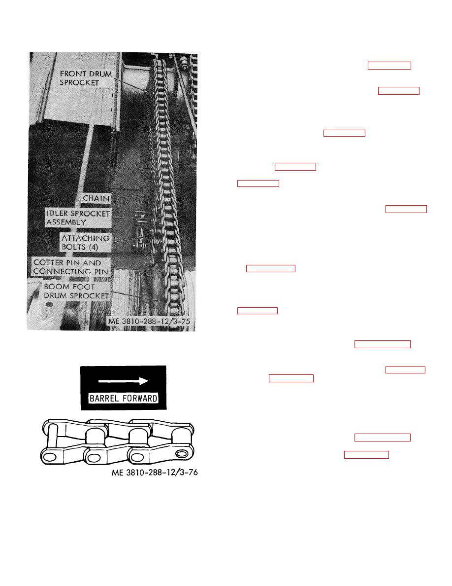
Figure 3-75. (Crowd chain idler sprocket assembly,
(1) Removal. Refer to paragraph 2-6 and
removal and replacement
remove the tagline winder.
(2) Repair. Drain oil from tagline winder by
removing the pipe plug (48) on the end plate, figure 3-82.
Refer to figure 3-82 and disassemble and repair the
tagline winder. The most probable cause of trouble will
be broken springs.
d. Upper Spreader. The upper spreader is
sometimes called the bridle assembly.
(1) Removal. Refer to paragraph 2-5 and
remove the upper spreader assembly.
(2) Repair. Refer to figure 3-83. Carefully
inspect sheave bushings for signs of wear or damage
and replace damaged bushings. Inspect sheaves for
wear, grooving, or cracks, and replace worn or damaged
sheaves. Inspect sheave pins for wear or scoring and
smooth small rough points with a fine file or emery cloth.
Figure 3-76. Crowd chain, direction of travel viewed
Replace severely
from above while entering drive sprocket in crowd out
direction.
3-90


