ROTARY JOINTS
SUB-SECTION 4C
SUB-SECTION 4C
ROTARY JOINTS
ROTARY JOINT (979J24)
8. Remove the capscrews and Iockwashers securing the
hydraulic swivel to the revolving frame deck. Then carefully
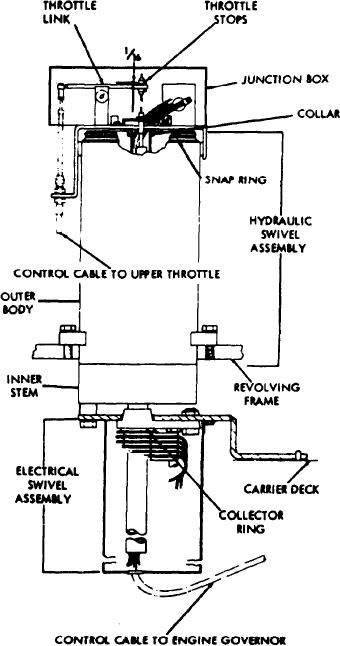
GENERAL. The rotary joint is mounted on the center of
the upper, and is the means by which the hydraulic and
electrical circuits in the upper are connected to their re-
spective circuits in the carrier.
The hydraulic swivel consists of an outerbody fixed to the
deck of the revolving frame and an inner stem fixed to the
carrier deck. This arrangement allows the upper to rotate
on the carrier without breaking a hydraulic connection.
The electrical swivel consists of a set of fixed circular
conductors and a set of collectors that make contact with
the conductors. The conductors are connected to the inner
stem of the hydraulic swivel so that the conductors will
rotate with the hydraulic swivel whenever the upper is
rotated. This maintains a continuous electrical connection
between the upper and carrier, regardless of the position of
the upper.
REMOVAL. The rotary joint must be removed to perform
any repairs. Remove the rotary joint as follows (see Figure
4C-1):
1. Disconnect the wound cable from the battery.
2. Tag and disconnect the electrical wires in the junction
box at the top of the hydraulic swivel.
3. Disconnect and remove the throttle cable. Loosen the
setscrews in the collar at the bottom of the junction box,
and remove the junction box.
4. Tag and remove the hydraulic lines attached to the outer
body of the swivel.
5. Tag and remove the hoses attached to the O-ring elbow
fittings in the lower portion of the inner stem.
6. Working either up from below the carrier or down
through the opening in the revolving frame, remove the
O-ring elbow fittings from the lower portion of the inner
stem.
7. Remove the two capscrews which connect the collector
assembly to the bottom of the hydraulic swivel.
Figure 4C-1. Rotary Joint (979J24)
4C-1

