SUB-SECTION 4D
CONTROL VALVES
TABLE 4D-3
TROUBLE, CAUSE AND REMEDY CHART (CONTINUED)
TROUBLE
REMEDY
PROBABLE CAUSE
Remove relief valve and check
No relief valve action (High
Small particle of dirt plugging
orifice in relief valve sub-
hole. If blocked, clear hole.
Pressure).
assembly.
Oil by-passing between spool
Replace valve.
Load will not hold.
and body.
Oil by-passing piston in cylinder.
Repair or replace cylinder.
Refer to above spool remedies.
Spool not centered.
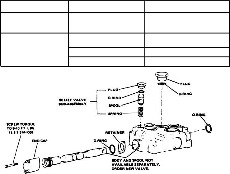
Figure 4D-6. Control Valve (36Z726)
3. Slide the spool out of its bore from the end cap end, and
placed. Check the valve spool for freedom of movement in
remove the O-rings from the spool bore.
the bore.
4. Screw out the plug which retains the relief valve and
4. Chock the relief valve for smooth movement in its bore.
remove the O-ring from the plug. Remove the spring and
The valve should move by its own weight.
relief valve.
ASSEMBLY. To assemble the valve, proceed as follows:
CLEANING, INSPECTION AND REPAIR. After the valve
has been disassembled, perform the following:
NOTE
1. Discard all old O-rings. Wash all parts in a clean mineral
Coat all parts with clean hydraulic oil to facilitate
oil solvent and place them on a clean surface for inspection.
reassembly and provide initial lubrication. Petroleum
jelly can be used to hold O-rings in place during reas-
2. Carefully remove burrs by light stoning or lapping. Be
sembly.
certain that there is no paint on the mating surfaces of the
valve body. Check all parts for wear. Replace if necessary.
1. Install the O-ring on the relief valve plug. lnstall the
spring in the relief valve bore, then install the relief valve on
3. Inspect the valve spool and bore for burrs and scoring. If
the spring. lnstall and tiqhten the relief valve plug. Do not
scoring is not deep enough to cause objectionable Ieakage,
over-tighten the plug.
the surfaces can be stoned or polished with crocus cloth. If
scoring is excessive the valve body and spool must be re-
2. Install new O-rings at each end of the spool bore.
4D-8

