SUB-SECTlON 4D
CONTROL VALVES
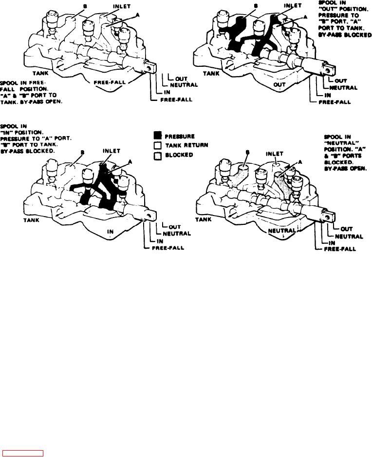
Figure 4D-11. Control Valve Operation (36Q70)
1. Be sure the valve is not subjected to pressure. Discon-
and remedy for each of the troubles listed. It should always
be remembered that pressure and delivery are factors which
nect and cap all lines, and disconnect the linkage from the
spool. Remove the valve from the machine.
are usually dependent upon each other. Adequate pressure
gauge equipment and a thorough understanding of the
2. Remove the screws which secure the wiper retainer, and
operation of the complete hydraulic system are essential to
remove the wiper retainer, wiper, retainer plate, and O-ring
diagnosing improper valve operation.
from the valve body.
OVERHAUL
3. Remove the screws which secure the end cap, and
remove the end cap.
GENERAL. Overhaul of this valve is limited to the replace-
ment of the relief valve assembly and seals. Replace the
4. Slide the spool out of its bore from the end cap end, and
complete valve when the required overhaul is beyond these
remove the O-ring from the spool bore.
limitations.
5. Screw out the plug which retains the relief valve, and
During disassembly, particular attention should be given to
remove the O-ring and back up ring from the plug. Remove
identification and orientation of parts for reassembly. The
the spring and poppet. Do not lose the pin in the relief
valve.
spool is selectively fitted to the valve body and must be
returned to the same body from which it was removed.
6. Remove the check valve plug, and remove the O-ring and
Figure 4D-12 is an exploded view of the valve showing the
back up ring from the plug. Remove the spring and poppet
proper relationship of the parts for reassembly. Refer to
from the valve.
this figure while disassembling and reassembling the valve.
CLEANING, INSPECTION AND REPAIR. After the valve
DISASSEMBLY. Disassemble the valve as follows:
has been disassembled, perform the following:
4D-15

