
TM -3810-300-24 & P2
INSPECTION.
Examine gages for cracked and broken lenses. Check gage terminals and mounting studs for damage. Check wiring for
damaged insulation or damaged terminals.
Engine Instruments - Installation. (Typical).
WARNING
ASSURE BATTERIES ARE DISCONNECTED BEFORE PERFORMING ANY MAINTENANCE ON THE
ELEC TRICAL SYSTEM.
1. Connect electrical leads as marked prior to removal.
2. Place gage into position on panel and secure with attaching hardware.
3. Secure instrument panel with attaching hardware.
FUNCTIONAL CHECK.
Start engine and observe indicators. (Refer to Operator's Handbook). Observe for proper functioning of selected
indicator. Further troubleshoot as necessary, any system malfunction not corrected by repair or replacement of indicator
or associated wiring.
Electric Switch.
REMOVAL.
WARNING
ASSURE BATTERIES ARE DISCONNECTED
BEFORE PERFORMING ANY MAINTENANCE
ON THE ELECTRICAL SYSTEM.
1. Remove attaching hardware to gain access to rear of
console.
2. Remove hardware securing switch to console;
remove switch.
3. Tag and disconnect electrical leads from switch; tape
leads.
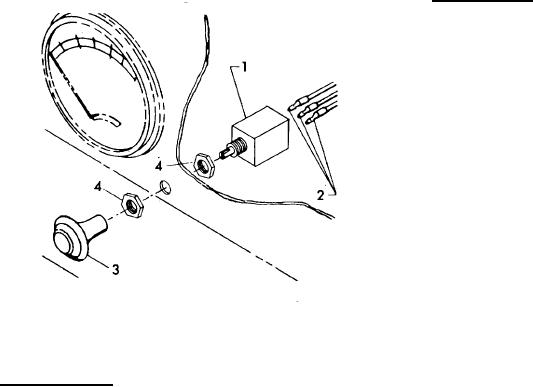
1. Switch
3. Knob
2. Electrical Leads
4. Nut
Electrical Switch.
INSPECTION.
1. Visually check switch for evidence of cracks, damaged connections or other damage.
2. Check wiring for damaged insulation or damaged terminals.
3. Perform the following check to determine switch serviceability.
a. Using an ohmmeter or continuity light, check for continuity between switch terminals with switch in ON or
activated position.
b. Position switch to OFF, ohmmeter should register zero (no continuity).
4-362