
TM 5-3810-300-24&P-3
1.2 Cylinder Head
gaskets and seals after the head is removed may reveal
the causes of any cylinder head problems.
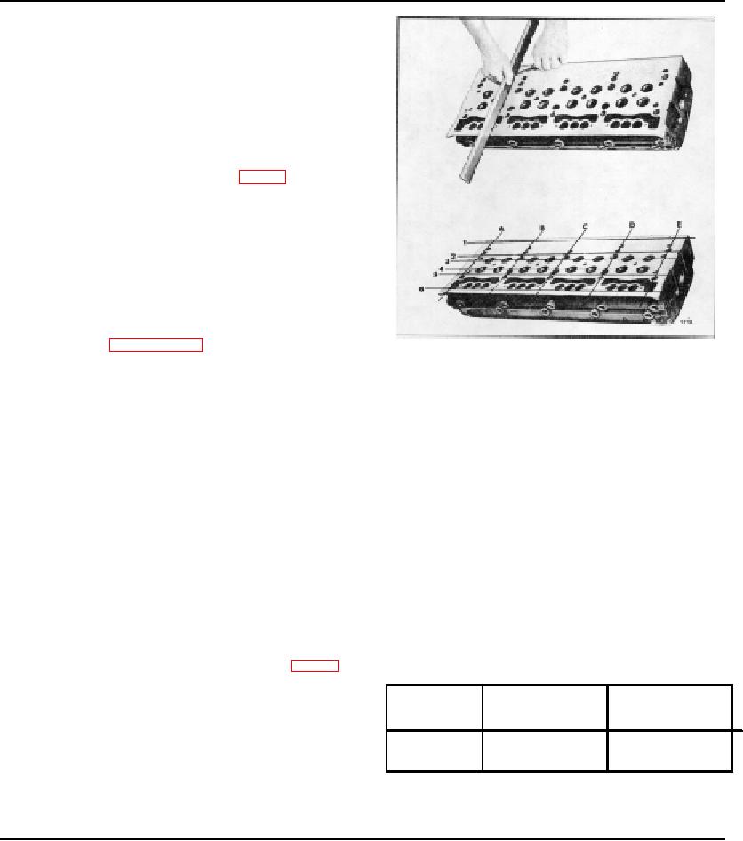
CAUTION: When placing the cylinder head
assembly on a bench, protect the cam followers
and injector spray tips, if the injectors were not
removed, by resting the valve side of the head
on 2 " thick wood blocks.
15. Place the cylinder head on its side and remove the
engine lifter brackets and gaskets. Then attach the
cylinder head holding plates J 3087-01 (Fig. 8) to raise
the head above the work bench.
16. Remove and discard the cylinder head compression
gaskets, oil seals and water seals.
17. After the cylinder head has been removed, drain the
lubricating oil from the engine. Draining the oil at this
time will remove any coolant that may have worked its
way to the oil pan when the head was removed.
Disassemble Cylinder Head
If complete disassembly of the cylinder head is
necessary, refer to Sections 1.2.1 and 1.2.2 for removal
Fig. 10 - Checking Bottom Face of Cylinder Head
of the exhaust valve and injector operating
mechanism.
the injector clamp bolts to 20-25 lb-ft (27-34
Nm) torque.
Clean Cylinder Head
After the cylinder head has been disassembled and all of
c.
Apply 80-100 psi (552-689 kPa) air pressure to
the plugs (except cup plugs) have been removed,
the water jacket. Then immerse the cylinder
thoroughly steam clean the head. If the water passages
head in a tank of water, previously heated to
are heavily coated with scale, remove the injector tubes
180-200'F or 82-93 C, for about twenty
and water nozzles. Then clean the cylinder head in the
minutes to thoroughly heat the head. Observe
same manner as outlined for cleaning the cylinder block
the water in the tank for bubbles which indicate
(Section 1.1).
a leak or crack. Check for leaks at the top and
bottom of the injector tubes, oil gallery, exhaust
Clean all of the cylinder head components with fuel oil
ports, fuel manifolds, and the top and bottom of
and dry them with compressed air.
the cylinder head.
Inspect Cylinder Head
d. Relieve the air pressure and remove the
1. Pressure check the cylinder head as follows:
cylinder head from the water tank.
Then
remove the plates, gaskets and injectors, and
a. Seal off the water holes in the head with steel
dry the head with compressed air.
plates and suitable rubber gaskets secured in
place with bolts and washers as shown in Fig. 9.
Drill and tap one of the cover plates for an air
Maximum
Maximum
hose connection.
Engine
Longitudinal
Transverse
b. Install scrap or dummy injectors to ensure
Warpage
Warpage
proper seating of the injector tubes. Dummy
injectors may be made from old injector nuts and
6-71
010"
.004"'
bodies --the injector spray tips are not
necessary. Tighten
TABLE 1
Page 34