
TM 5-3810-300-24&P-3
GEAR TRAIN AND TIMING 1.7.1
the vibration damper, or crankshaft pulley, whichever
is used.
9. Rotate the crankshaft in the direction of rotation
slowly until the hand on the dial indicator just stops
moving.
10. Rotate the crankshaft in the direction of rotation until
the indicator hand just starts to move. Reset dial to
"0". Continue turning the crank-shaft slowly until the
indicator reading is .010" -- then stop turning.
11. Scribe a line on the damper (or crankshaft pulley) in
line with the end of the pointer.
12. Rotate the crankshaft opposite the direction of
rotation slowly until the hand on the dial indicator just
stops moving.
13. Rotate the crankshaft opposite the direction of
rotation until the indicator hand just starts to move.
Fig. 2 - Pointer Installation For Marking
Reset dial to "0". Continue turning the crankshaft
Top-Dead-Center
slowly until indicator reading is .010"--then stop
turning.
reaches the end of its upward travel. Remove the
rod and turn the crankshaft opposite the direction of
14. Scribe a second line on the vibration damper (or
rotation between 1/16 and 1/8 of a turn.
crankshaft pulley) in the same manner as in Step 11.
6. Select a dial indicator with .001" graduations and
15. Scribe a third line halfway between the first two lines.
with a spindle movement of at least 1". Use suitable
This is positive top-dead-center. The three scribed
mounting attachments for the indicator so that it can
lines are shown on the crankshaft pulley in Fig. 2.
be mounted over the injector hole in the cylinder
Remove the indicator from the engine.
head. Provide an extension for the spindle of the
indicator. The extension must be long enough to
contact the piston as it approaches its upper
position.
7. Mount the indicator over the injector hole and tighten
mountings sufficiently to hold the indicator rigid.
The mounting leg may be threaded into the rocker
cover stud; or the stud may be removed from the
cylinder head and the leg threaded into the tapped
hole, depending upon the length of the rod used in
making up the mounting attachments. Make sure
that the spindle extension is free in the injector hole,
does not bind, and is free to travel its full 1"
movement.
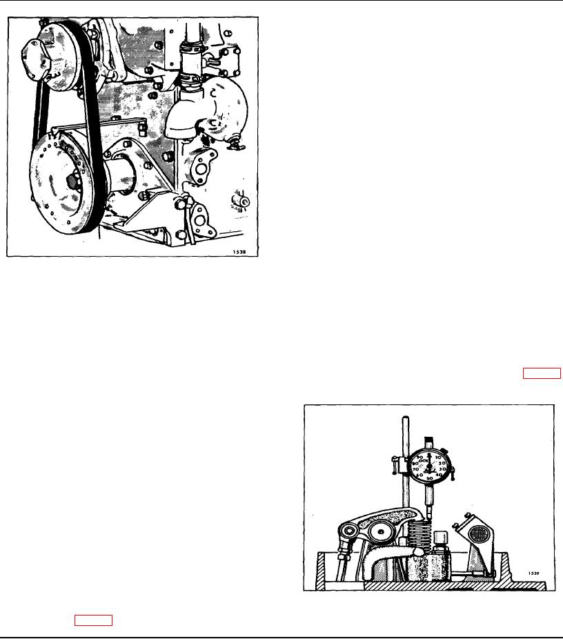
8. Provide a suitable pointer and attach it to the
Fig. 3 - Checking Engine Timing By
crankshaft front cover or engine front end plate as
Measuring Injector Depression
illustrated in Fig. 2. The pointer should ex-tend over
Page 115