
TM 5-3810-300-24&P-3
BLOWER DRIVE GEAR 1.7.6
4. Connect the oil line (Fig. 3).
5. Install the blower as outlined in Section 3.4 and
secure the seal (61) and clamp (52), Fig. 5.
6. Insert the blower drive shaft into the blower rotor
gear hub. The end without the groove for the ring
must be inserted first.
7. Lock the drive shaft in place by installing the ring in
the groove provided in the coupling cam.
8. Re-install the flywheel and flywheel housing as
described in Sections 1.4 and 1.5 and install the
remaining bolts that secure the blower drive gear
and support assembly.
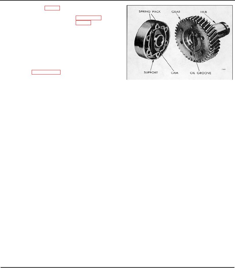
Fig. 7 - Relation of Blower Drive Cam
to Oil Grooves in Gear Hub
Page 136